Electrical Circuits (Diploma 3rd Sem)
Cheatsheet Content
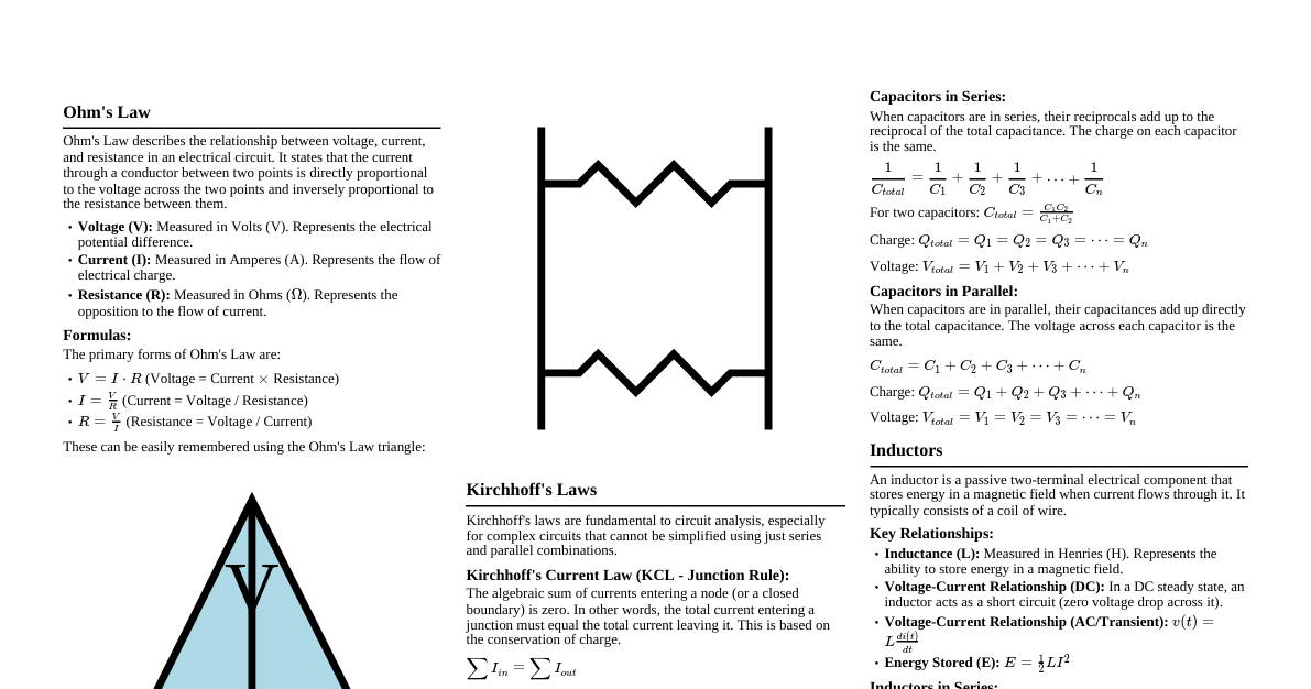
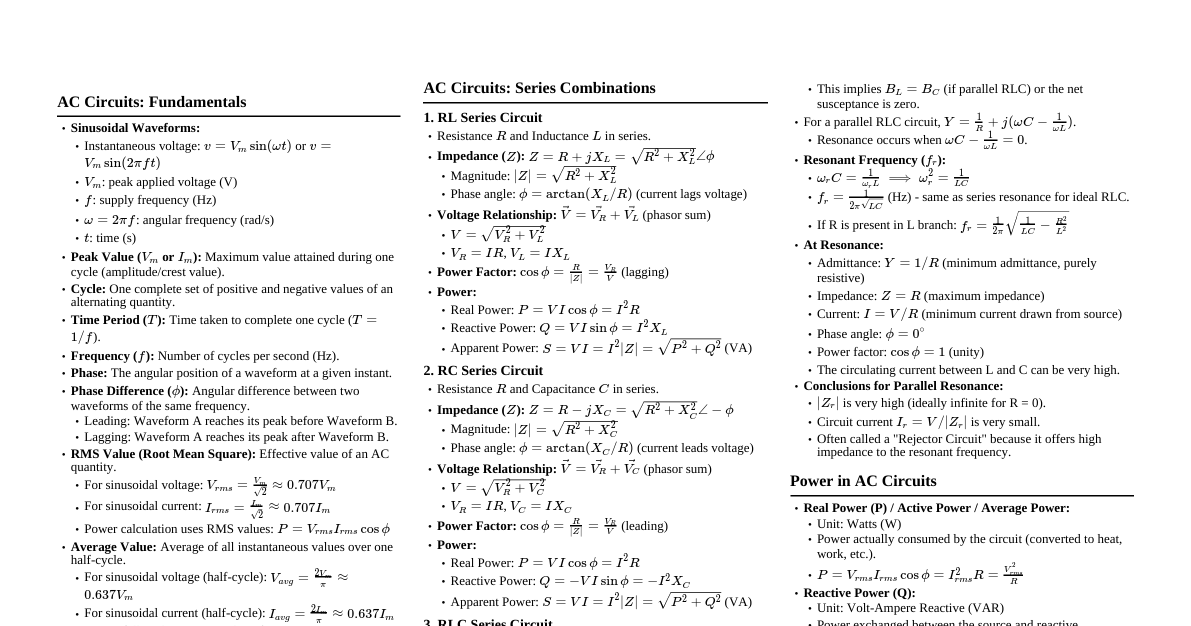
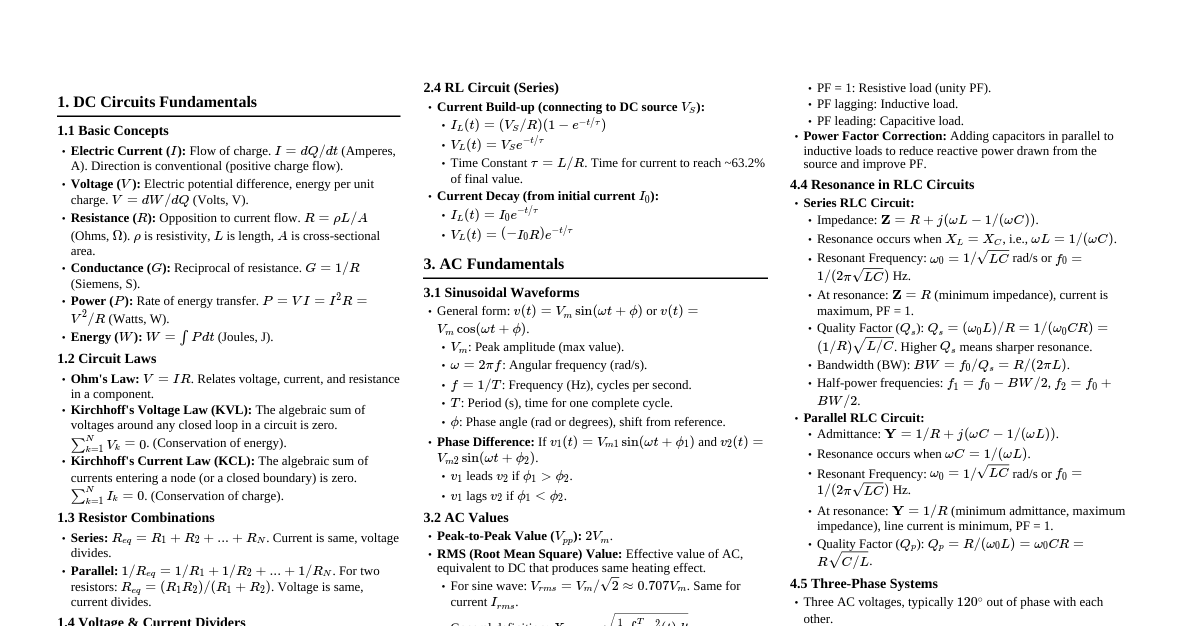
1. Basic Concepts & Definitions Charge ($Q$): Fundamental property of matter. Unit: Coulomb (C). Electron charge: $e = 1.602 \times 10^{-19}$ C Current ($I$): Rate of flow of charge. Unit: Ampere (A). $I = \frac{dQ}{dt}$ Voltage ($V$ or $E$): Potential difference, work done per unit charge. Unit: Volt (V). $V = \frac{dW}{dQ}$ Resistance ($R$): Opposition to current flow. Unit: Ohm ($\Omega$). $R = \rho \frac{L}{A}$ ($\rho$: resistivity, $L$: length, $A$: area) Power ($P$): Rate of doing work. Unit: Watt (W). $P = VI = I^2R = \frac{V^2}{R}$ Energy ($W$): Capacity to do work. Unit: Joule (J) or kWh. $W = Pt = VIt$ 2. Ohm's Law States that $V \propto I$ for a given resistance. Formula: $V = IR$ Forms: $I = \frac{V}{R}$, $R = \frac{V}{I}$ 3. Resistors in Series and Parallel Series Connection Total Resistance: $R_{eq} = R_1 + R_2 + R_3 + ...$ Current: $I_{total} = I_1 = I_2 = I_3 = ...$ (Same current through each resistor) Voltage Division: $V_x = V_{total} \frac{R_x}{R_{eq}}$ Parallel Connection Total Resistance: $\frac{1}{R_{eq}} = \frac{1}{R_1} + \frac{1}{R_2} + \frac{1}{R_3} + ...$ For two resistors: $R_{eq} = \frac{R_1 R_2}{R_1 + R_2}$ Voltage: $V_{total} = V_1 = V_2 = V_3 = ...$ (Same voltage across each resistor) Current Division: $I_x = I_{total} \frac{R_{total}}{R_x}$ or $I_1 = I_{total} \frac{R_2}{R_1+R_2}$ (for two resistors) 4. Kirchhoff's Laws Kirchhoff's Current Law (KCL) Algebraic sum of currents entering a node (junction) is zero. $\sum I_{in} = \sum I_{out}$ Kirchhoff's Voltage Law (KVL) Algebraic sum of all voltages around any closed loop is zero. $\sum V_{drops} = \sum V_{rises}$ (or $\sum V = 0$) 5. Network Theorems Superposition Theorem In a linear circuit with multiple independent sources, the total current/voltage in any element is the algebraic sum of the currents/voltages produced by each source acting independently. Steps: Consider one independent source at a time. Replace other voltage sources with short circuits, current sources with open circuits. Calculate desired quantity for that source. Repeat for all sources and sum the results. Thevenin's Theorem Any linear two-terminal circuit can be replaced by an equivalent circuit consisting of a single voltage source ($V_{Th}$) in series with a single resistor ($R_{Th}$). $V_{Th}$: Open-circuit voltage across the terminals. $R_{Th}$: Equivalent resistance looking into the terminals with all independent sources turned off (voltage sources shorted, current sources opened). Norton's Theorem Any linear two-terminal circuit can be replaced by an equivalent circuit consisting of a single current source ($I_N$) in parallel with a single resistor ($R_N$). $I_N$: Short-circuit current through the terminals. $R_N$: Equivalent resistance looking into the terminals with all independent sources turned off ($R_N = R_{Th}$). Maximum Power Transfer Theorem Maximum power is transferred from a source to a load when the load resistance ($R_L$) is equal to the Thevenin equivalent resistance ($R_{Th}$) of the source circuit. $P_{max} = \frac{V_{Th}^2}{4R_{Th}}$ 6. Capacitors & Inductors Capacitor ($C$) Stores energy in an electric field. Unit: Farad (F). Relationship: $Q = CV$ Current: $I = C \frac{dV}{dt}$ Voltage: $V = \frac{1}{C} \int I dt$ Energy Stored: $E = \frac{1}{2}CV^2$ Series: $\frac{1}{C_{eq}} = \frac{1}{C_1} + \frac{1}{C_2} + ...$ Parallel: $C_{eq} = C_1 + C_2 + ...$ Behaves as short circuit at DC steady state. Inductor ($L$) Stores energy in a magnetic field. Unit: Henry (H). Voltage: $V = L \frac{dI}{dt}$ Current: $I = \frac{1}{L} \int V dt$ Energy Stored: $E = \frac{1}{2}LI^2$ Series: $L_{eq} = L_1 + L_2 + ...$ Parallel: $\frac{1}{L_{eq}} = \frac{1}{L_1} + \frac{1}{L_2} + ...$ Behaves as open circuit at DC steady state. 7. AC Fundamentals Alternating Current (AC): Current that periodically reverses direction. Sinusoidal Waveform: $v(t) = V_m \sin(\omega t + \phi)$ or $i(t) = I_m \sin(\omega t + \phi)$ $V_m, I_m$: Peak (maximum) value $\omega = 2\pi f$: Angular frequency (rad/s) $f = \frac{1}{T}$: Frequency (Hz) $T$: Period (s) $\phi$: Phase angle (rad or degrees) RMS Value: Root Mean Square value, effective value. For sine wave: $V_{rms} = \frac{V_m}{\sqrt{2}}$, $I_{rms} = \frac{I_m}{\sqrt{2}}$ Average Value: For full cycle sine wave: $0$ For half cycle (rectified): $V_{avg} = \frac{2V_m}{\pi}$ Form Factor: $\frac{RMS Value}{Average Value}$ (For sine wave: $1.11$) Peak Factor: $\frac{Maximum Value}{RMS Value}$ (For sine wave: $1.414$) 8. Phasor Representation A complex number representing the amplitude and phase of a sinusoidal quantity. Rectangular form: $Z = R + jX$ Polar form: $Z = |Z| \angle \theta$ Conversion: $|Z| = \sqrt{R^2 + X^2}$ $\theta = \arctan(\frac{X}{R})$ $R = |Z| \cos \theta$ $X = |Z| \sin \theta$ $j = \sqrt{-1}$ (phasor operator, rotates by $90^\circ$ counter-clockwise) 9. AC Circuit Analysis Impedance ($Z$): Total opposition to AC current (resistance + reactance). Unit: Ohm ($\Omega$). Resistor: $Z_R = R \angle 0^\circ = R$ Inductor: $Z_L = j\omega L = \omega L \angle 90^\circ$ Capacitor: $Z_C = \frac{1}{j\omega C} = -j\frac{1}{\omega C} = \frac{1}{\omega C} \angle -90^\circ$ Ohm's Law for AC: $V = IZ$ Admittance ($Y$): Reciprocal of impedance. $Y = \frac{1}{Z} = G + jB$. Unit: Siemens (S). $G$: Conductance, $B$: Susceptance 10. AC Power Apparent Power ($S$): Total power delivered. Unit: Volt-Ampere (VA). $S = VI^* = |V||I|$ (where $I^*$ is conjugate of $I$) Real Power ($P$): Average power consumed by resistance. Unit: Watt (W). $P = |V||I| \cos \phi = I^2 R = \text{Re}(S)$ Reactive Power ($Q$): Power exchanged between source and reactive components. Unit: Volt-Ampere Reactive (VAR). $Q = |V||I| \sin \phi = I^2 X = \text{Im}(S)$ Power Triangle: $S^2 = P^2 + Q^2$ Power Factor (PF): $\cos \phi = \frac{P}{S}$. Lagging PF: Inductive load (current lags voltage) Leading PF: Capacitive load (current leads voltage) 11. Resonance in RLC Circuits Series RLC Circuit Resonance occurs when $X_L = X_C$. Resonant Frequency: $f_0 = \frac{1}{2\pi \sqrt{LC}}$ At resonance: Impedance is minimum and purely resistive ($Z = R$). Current is maximum. PF is unity. Quality Factor ($Q_s$): $\frac{\omega_0 L}{R} = \frac{1}{\omega_0 C R} = \frac{1}{R} \sqrt{\frac{L}{C}}$ Bandwidth ($BW$): $f_2 - f_1 = \frac{f_0}{Q_s} = \frac{R}{2\pi L}$ Parallel RLC Circuit Resonance occurs when $X_L = X_C$. Resonant Frequency: $f_0 = \frac{1}{2\pi \sqrt{LC}}$ (for ideal parallel RLC) At resonance: Impedance is maximum and purely resistive ($Z = R$). Current (total) is minimum. PF is unity. Quality Factor ($Q_p$): $\frac{R}{\omega_0 L} = \omega_0 C R = R \sqrt{\frac{C}{L}}$ Bandwidth ($BW$): $f_2 - f_1 = \frac{f_0}{Q_p} = \frac{1}{2\pi CR}$ 12. Three-Phase Systems Advantages: More power, smoother torque, less material. Phase Sequence: R-Y-B or A-B-C. Star (Wye) Connection: Line Voltage ($V_L$) and Phase Voltage ($V_P$): $V_L = \sqrt{3} V_P$ Line Current ($I_L$) and Phase Current ($I_P$): $I_L = I_P$ Delta (Mesh) Connection: Line Voltage ($V_L$) and Phase Voltage ($V_P$): $V_L = V_P$ Line Current ($I_L$) and Phase Current ($I_P$): $I_L = \sqrt{3} I_P$ Total Power (Balanced 3-Phase): Real Power: $P = \sqrt{3} V_L I_L \cos \phi = 3 V_P I_P \cos \phi$ Reactive Power: $Q = \sqrt{3} V_L I_L \sin \phi = 3 V_P I_P \sin \phi$ Apparent Power: $S = \sqrt{3} V_L I_L = 3 V_P I_P$