Electrical Engineering Essentials
Cheatsheet Content
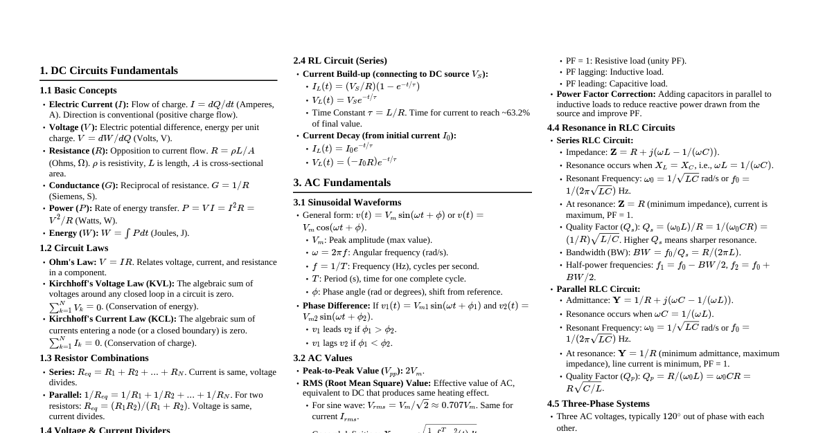
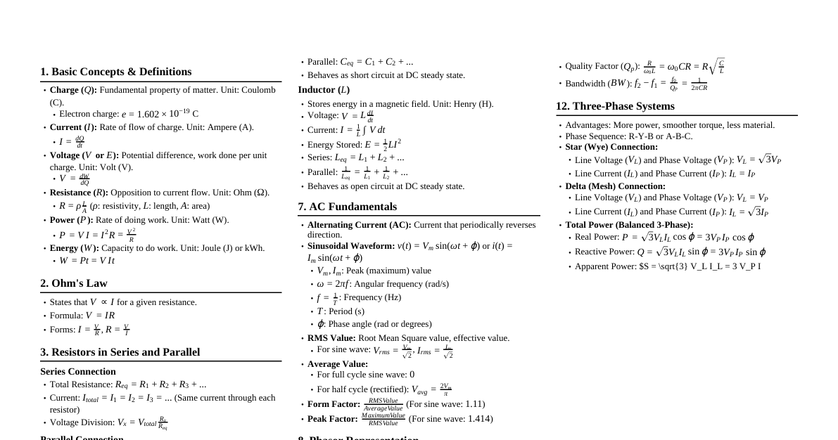
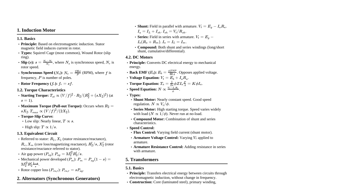
D.C. Circuits Ohm's Law & Power Ohm's Law: $V = IR$, where $V$ is voltage, $I$ is current, and $R$ is resistance. Electrical Power: $P = VI = I^2R = V^2/R$. Measured in Watts (W). Energy: $E = Pt$. Measured in Joules (J) or Watt-hours (Wh). Resistors in Series & Parallel Series: $R_{eq} = R_1 + R_2 + ... + R_n$. Current is same, voltage divides. Parallel: $\frac{1}{R_{eq}} = \frac{1}{R_1} + \frac{1}{R_2} + ... + \frac{1}{R_n}$. Voltage is same, current divides. For two resistors: $R_{eq} = \frac{R_1 R_2}{R_1 + R_2}$. Kirchhoff's Laws Kirchhoff's Current Law (KCL): The algebraic sum of currents entering a node is zero. $\sum I_{in} = \sum I_{out}$. Kirchhoff's Voltage Law (KVL): The algebraic sum of voltages around any closed loop is zero. $\sum V = 0$. Circuit Analysis Techniques Source Transformation: Convert voltage sources to current sources and vice versa. Voltage source $V_S$ in series with $R_S$ $\leftrightarrow$ Current source $I_S = V_S/R_S$ in parallel with $R_S$. Mesh Analysis: Apply KVL to independent loops. Assign mesh currents ($I_1, I_2, ...$) to each loop. Write KVL equations for each mesh. Solve the system of equations for mesh currents. Nodal Analysis: Apply KCL at independent nodes. Choose a reference node (ground). Assign node voltages ($V_1, V_2, ...$) to other nodes. Write KCL equations for each non-reference node. Solve the system of equations for node voltages. Star-Delta / Delta-Star Transformations: Convert between Y- ($\text{Star}$) and $\Delta$- ($\text{Delta}$) connected resistors. Delta to Star: $R_1 = \frac{R_{12}R_{31}}{R_{12}+R_{23}+R_{31}}$ $R_2 = \frac{R_{12}R_{23}}{R_{12}+R_{23}+R_{31}}$ $R_3 = \frac{R_{23}R_{31}}{R_{12}+R_{23}+R_{31}}$ Star to Delta: $R_{12} = \frac{R_1R_2+R_2R_3+R_3R_1}{R_3}$ $R_{23} = \frac{R_1R_2+R_2R_3+R_3R_1}{R_1}$ $R_{31} = \frac{R_1R_2+R_2R_3+R_3R_1}{R_2}$ Network Theorems Superposition Theorem: In a linear circuit with multiple independent sources, the current/voltage at any element is the sum of the currents/voltages produced by each source acting independently. Turn off all but one independent source (voltage sources become short circuits, current sources become open circuits). Calculate the response due to that active source. Repeat for all independent sources and sum the individual responses. Thevenin's Theorem: Any linear two-terminal circuit can be replaced by an equivalent circuit consisting of a voltage source ($V_{Th}$) in series with a resistor ($R_{Th}$). $V_{Th}$: Open-circuit voltage across the terminals. $R_{Th}$: Equivalent resistance looking into the terminals with all independent sources turned off. Norton's Theorem: Any linear two-terminal circuit can be replaced by an equivalent circuit consisting of a current source ($I_N$) in parallel with a resistor ($R_N$). $I_N$: Short-circuit current between the terminals. $R_N$: Equivalent resistance looking into the terminals with all independent sources turned off ($R_N = R_{Th}$). Maximum Power Transfer Theorem: A load resistor $R_L$ receives maximum power from a linear circuit when $R_L$ is equal to the Thevenin resistance ($R_{Th}$) of the circuit as seen from the load terminals. Maximum power $P_{max} = \frac{V_{Th}^2}{4R_{Th}}$. A.C. Circuits Basic Definitions & Values Alternating Voltage/Current: Varies sinusoidally with time. $v(t) = V_m \sin(\omega t + \phi)$. $V_m$: Peak amplitude. $\omega = 2\pi f$: Angular frequency (rad/s). $f = 1/T$: Frequency (Hz), $T$ is period (s). $\phi$: Phase angle (rad or degrees). Average Value: For a full cycle of a sine wave, the average value is 0. For a half-cycle, $V_{avg} = \frac{2V_m}{\pi}$. RMS Value (Root Mean Square): Effective value of AC. $V_{RMS} = \frac{V_m}{\sqrt{2}}$. Power calculations use RMS values. Phasors: Represent sinusoidal quantities as complex numbers. $V = V_{RMS} \angle \phi = V_{RMS} (\cos\phi + j\sin\phi)$. Phase Difference: The difference in phase angles between two phasors. Indicates which waveform leads or lags. Single-Phase AC Circuits Components: Resistor (R): $V_R = IR$, $Z_R = R \angle 0^\circ$. Voltage and current are in phase. Inductor (L): $V_L = I(j\omega L)$, $Z_L = j\omega L = \omega L \angle 90^\circ$. Voltage leads current by $90^\circ$. $X_L = \omega L$ (inductive reactance). Capacitor (C): $V_C = I(\frac{1}{j\omega C})$, $Z_C = \frac{1}{j\omega C} = \frac{1}{\omega C} \angle -90^\circ$. Current leads voltage by $90^\circ$. $X_C = \frac{1}{\omega C}$ (capacitive reactance). Impedance (Z): Total opposition to current in AC circuits. $Z = R + jX$, where $X$ is reactance ($X_L - X_C$). Unit: Ohms ($\Omega$). Magnitude: $|Z| = \sqrt{R^2 + X^2}$. Phase angle: $\theta = \arctan(X/R)$. Admittance (Y): Reciprocal of impedance. $Y = 1/Z = G + jB$, where $G$ is conductance, $B$ is susceptance. Unit: Siemens (S). Series RLC Circuit: $Z_{total} = R + j(\omega L - \frac{1}{\omega C})$. Parallel RLC Circuit: Admittance $Y_{total} = \frac{1}{R} + j(\omega C - \frac{1}{\omega L})$. Power in AC Circuits Real Power (P): Average power consumed by resistive components (W). $P = V_{RMS} I_{RMS} \cos \phi = I_{RMS}^2 R = \frac{V_{RMS}^2}{R}$. Reactive Power (Q): Power exchanged between source and reactive components (VAR). $Q = V_{RMS} I_{RMS} \sin \phi = I_{RMS}^2 X = \frac{V_{RMS}^2}{X}$. Positive for inductive loads, negative for capacitive loads. Apparent Power (S): Total power supplied by the source (VA). $S = V_{RMS} I_{RMS}$. In complex form, $S = P + jQ$. Magnitude: $|S| = \sqrt{P^2 + Q^2}$. Power Factor (PF): $\cos \phi = P/S$. Indicates how effectively power is being used. Lagging PF for inductive loads, leading PF for capacitive loads. Power Factor Correction: Adding capacitors in parallel with inductive loads to improve PF (make it closer to 1). Resonance Series Resonance: Occurs when $X_L = X_C$, so $\omega L = \frac{1}{\omega C}$. Resonant frequency: $f_0 = \frac{1}{2\pi\sqrt{LC}}$. At resonance, impedance is purely resistive ($Z=R$), current is maximum, and power factor is unity (1). Quality Factor (Q-factor): $Q = \frac{\omega_0 L}{R} = \frac{1}{\omega_0 C R}$. Measures the sharpness of resonance. Bandwidth (BW): $BW = f_2 - f_1 = f_0/Q$. $f_1, f_2$ are half-power frequencies. Parallel Resonance: Occurs when the susceptance of the inductive and capacitive branches cancel out. Resonant frequency: $f_0 = \frac{1}{2\pi\sqrt{LC}}$ (for ideal parallel RLC). At resonance, impedance is maximum (approaching infinity for ideal parallel LC), current from source is minimum, and power factor is unity. Three-Phase Voltages Generated with three sinusoidal voltages having the same magnitude and frequency but displaced by $120^\circ$ in phase. Star (Y) Connection: Line voltage $V_L = \sqrt{3} V_{ph}$. Line current $I_L = I_{ph}$. Total power: $P = \sqrt{3} V_L I_L \cos\phi$. Delta ($\Delta$) Connection: Line voltage $V_L = V_{ph}$. Line current $I_L = \sqrt{3} I_{ph}$. Total power: $P = \sqrt{3} V_L I_L \cos\phi$. Single Phase Transformer Working Principle: Based on mutual induction. An alternating voltage applied to the primary winding creates a changing magnetic flux in the core, which induces an EMF in the secondary winding. EMF Equation: $E = 4.44 f \Phi_m N$, where $f$ is frequency, $\Phi_m$ is max flux, $N$ is number of turns. Transformation Ratio (k): Ratio of secondary voltage to primary voltage, or secondary turns to primary turns. $k = \frac{V_2}{V_1} = \frac{N_2}{N_1} = \frac{I_1}{I_2}$ (for ideal transformer). Types: Step-up (k > 1), Step-down (k Actual (Practical) Transformer: Losses: Core losses (Iron losses): Hysteresis loss, Eddy current loss. Depend on flux density and frequency. Minimized by using laminated core and suitable core material. Copper losses: $I^2R$ losses in primary and secondary windings. Depend on current. Efficiency ($\eta$): $\eta = \frac{\text{Output Power}}{\text{Input Power}} = \frac{\text{Output Power}}{\text{Output Power} + \text{Losses}}$. Max efficiency occurs when copper losses = core losses. Voltage Regulation: $VR = \frac{V_{no-load} - V_{full-load}}{V_{full-load}} \times 100\%$. Ideally 0%. Equivalent Circuit: Represents non-ideal characteristics (winding resistance, leakage reactance, magnetizing reactance, core losses). Autotransformer: Uses a single winding for both primary and secondary, with a tap for secondary connection. Smaller, more efficient for small voltage changes. Electrical Machines DC Motor Principle of Operation: When a current-carrying conductor is placed in a magnetic field, it experiences a force (Lorentz force). In a DC motor, this force produces torque, causing rotation. Back EMF ($E_b$): $E_b = K\Phi\omega$, generated in the armature opposing the applied voltage. $V_a = E_b + I_a R_a$. Torque Equation: $T = K\Phi I_a$. Speed Control: Armature Voltage Control: Varying $V_a$ (below rated speed). Field Flux Control: Varying $\Phi$ (above rated speed). Applications: Electric vehicles, industrial drives, cranes, pumps. DC Generator Principle: Converts mechanical energy to electrical energy based on Faraday's law of electromagnetic induction. Generated EMF ($E_g$): $E_g = \frac{\Phi Z N P}{60 A}$, where $\Phi$ is flux/pole, $Z$ is total conductors, $N$ is speed (rpm), $P$ is poles, $A$ is parallel paths. AC Motors Three-Phase Induction Motor: Principle: Rotating magnetic field produced by stator currents induces currents in rotor windings, creating torque. Synchronous Speed: $N_s = \frac{120 f}{P}$ (rpm). Slip (s): $s = \frac{N_s - N_r}{N_s}$, where $N_r$ is rotor speed. Rotor frequency $f_r = s f$. Torque-Slip Characteristics: Torque is proportional to slip for small slip, peaks at a certain slip, then decreases. Starting Methods: DOL (Direct Online), Star-Delta, Auto-transformer, Rotor resistance. Speed Control: Varying frequency ($f$). Varying number of poles ($P$). Varying slip (e.g., rotor resistance control for wound rotor). Synchronous Motor: Principle: Rotor locks into step with the rotating magnetic field and runs at synchronous speed ($N_s$). Requires DC excitation for rotor. Advantages: Constant speed, can operate at leading, lagging, or unity power factor. Applications: Power factor correction, constant speed drives. Single-Phase Induction Motors: Not self-starting; require auxiliary means (e.g., capacitor, shaded pole) to create a starting torque. Types: Split-phase, Capacitor-start, Capacitor-start-capacitor-run, Shaded pole. BLDC Motors (Brushless DC Motors): Electronically commutated DC motors. No brushes or commutator. High efficiency, long life, quiet operation, high power density. Used in drones, electric vehicles, robotics. Semiconductor Diodes P-N Junction Diode Construction: Formed by joining P-type (majority holes) and N-type (majority electrons) semiconductor materials, creating a P-N junction. Working Principle: Forward Bias: P-side connected to positive, N-side to negative. External voltage overcomes barrier potential, depletion region narrows, allowing current flow. Reverse Bias: P-side connected to negative, N-side to positive. Depletion region widens, blocking current flow (except for small leakage current). Breakdown Voltage: Voltage at which reverse current increases sharply due to avalanche or Zener effect. Characteristics: Non-linear I-V characteristic. Low forward voltage drop (e.g., 0.7V for Silicon, 0.3V for Germanium). High reverse resistance. Applications: Rectifiers (AC to DC conversion - half-wave, full-wave bridge), voltage clamping, signal demodulation. Special Purpose Diodes Zener Diode: Designed to operate in reverse breakdown region. Maintains a constant voltage (Zener voltage, $V_Z$) across its terminals despite varying current. Applications: Voltage regulation, reference voltage. LED (Light Emitting Diode): A P-N junction diode that emits light when forward biased due to recombination of electrons and holes. Applications: Indicator lights, displays, general lighting, optical communication. Photodiode: Converts light energy into electrical current. Used in optical sensors. Varactor Diode: A voltage-controlled capacitor. Used in tuning circuits. Transistors BJT (Bipolar Junction Transistor) Structure: Three layers of semiconductor material (NPN or PNP) with three terminals: Emitter (E), Base (B), Collector (C). Operation: A small current at the base ($I_B$) controls a larger current between the collector and emitter ($I_C$). Configurations: Common Emitter (CE): Input at base, output at collector. High current gain ($\beta = I_C/I_B$), voltage gain, and power gain. Output is phase-inverted. Common Collector (CC - Emitter Follower): Input at base, output at emitter. High input impedance, low output impedance. Voltage gain near 1. Used as a buffer. Common Base (CB): Input at emitter, output at collector. Very low input impedance, high output impedance. Current gain near 1 ($\alpha = I_C/I_E$). Used for high-frequency applications. Operating Regions: Cut-off: Both junctions reverse biased, transistor OFF. Active: Base-emitter forward biased, base-collector reverse biased. Used for amplification. Saturation: Both junctions forward biased, transistor ON (switch). FET (Field-Effect Transistor) Structure: Three terminals: Gate (G), Source (S), Drain (D). JFET (Junction FET): Uses a reverse-biased P-N junction for the gate. MOSFET (Metal-Oxide-Semiconductor FET): Uses an insulated gate (metal oxide layer). Most common type. Enhancement-mode MOSFET (E-MOSFET): Requires a positive (for n-channel) or negative (for p-channel) $V_{GS}$ to create a conductive channel. Normally OFF. Depletion-mode MOSFET (D-MOSFET): Has a conductive channel even with $V_{GS}=0$. Can operate in both depletion and enhancement modes. Operation: The voltage applied to the gate ($V_{GS}$) controls the current flow between the drain and source ($I_D$) by modulating the width of a channel. Voltage-controlled device. Characteristics: High input impedance (especially MOSFETs), lower noise than BJTs. Applications: Amplification: Used in amplifiers, especially where high input impedance is critical. Switching: Excellent electronic switches, widely used in digital circuits (CMOS technology) and power electronics due to high switching speed and low ON-resistance. Operational Amplifiers (Op-Amps) Ideal Op-Amp Characteristics: Infinite input impedance ($Z_{in} = \infty$). Zero output impedance ($Z_{out} = 0$). Infinite open-loop gain ($A = \infty$). Infinite bandwidth. Zero input offset voltage. Golden Rules (for negative feedback): No current flows into the input terminals ($I_+ = I_- = 0$). The voltage between the input terminals is zero ($V_+ = V_-$). Basic Configurations: Inverting Amplifier: $V_{out} = -\frac{R_f}{R_{in}} V_{in}$. Non-inverting Amplifier: $V_{out} = (1 + \frac{R_f}{R_1}) V_{in}$. Voltage Follower (Buffer): $V_{out} = V_{in}$. Provides high input impedance and low output impedance. Summing Amplifier: $V_{out} = -R_f (\frac{V_1}{R_1} + \frac{V_2}{R_2} + ...)$. Integrator: $V_{out} = -\frac{1}{RC} \int V_{in} dt$. Differentiator: $V_{out} = -RC \frac{dV_{in}}{dt}$. Applications: Amplifiers, filters, oscillators, comparators, active rectifiers. Digital Electronics Number Systems Binary (Base-2): Digits 0, 1. (e.g., $101_2 = 5_{10}$) Decimal (Base-10): Digits 0-9. Hexadecimal (Base-16): Digits 0-9, A-F. (e.g., $A5_{16} = 165_{10}$) Conversion: Techniques for converting between bases. Logic Gates Basic Gates: AND, OR, NOT (Inverter). Universal Gates: NAND, NOR (can implement any other logic function). Derived Gates: XOR, XNOR. Gate Boolean Expression Truth Table AND $Y = A \cdot B$ 00=0, 01=0, 10=0, 11=1 OR $Y = A + B$ 00=0, 01=1, 10=1, 11=1 NOT $Y = \bar{A}$ 0=1, 1=0 NAND $Y = \overline{A \cdot B}$ 00=1, 01=1, 10=1, 11=0 NOR $Y = \overline{A + B}$ 00=1, 01=0, 10=0, 11=0 XOR $Y = A \oplus B = \bar{A}B + A\bar{B}$ 00=0, 01=1, 10=1, 11=0 Boolean Algebra Commutative Laws: $A+B = B+A$, $A \cdot B = B \cdot A$. Associative Laws: $A+(B+C) = (A+B)+C$, $A(BC) = (AB)C$. Distributive Laws: $A(B+C) = AB+AC$, $A+(BC) = (A+B)(A+C)$. Identity Laws: $A+0=A$, $A \cdot 1=A$. Complement Laws: $A+\bar{A}=1$, $A \cdot \bar{A}=0$. De Morgan's Theorems: $\overline{A+B} = \bar{A} \cdot \bar{B}$, $\overline{A \cdot B} = \bar{A} + \bar{B}$. Combinational Logic Output depends only on current inputs. Adders: Half Adder, Full Adder. Multiplexers (MUX): Selects one of several input signals and forwards it to a single output line. Demultiplexers (DEMUX): Takes a single input and routes it to one of several outputs. Encoders/Decoders. Sequential Logic Output depends on current inputs and past states (memory). Flip-Flops: Basic memory elements (SR, D, JK, T). Triggered by clock edges. Registers: Group of flip-flops to store multiple bits. Counters: Count clock pulses (e.g., ripple counter, synchronous counter).