Electrical Science: AC Circuits
Cheatsheet Content
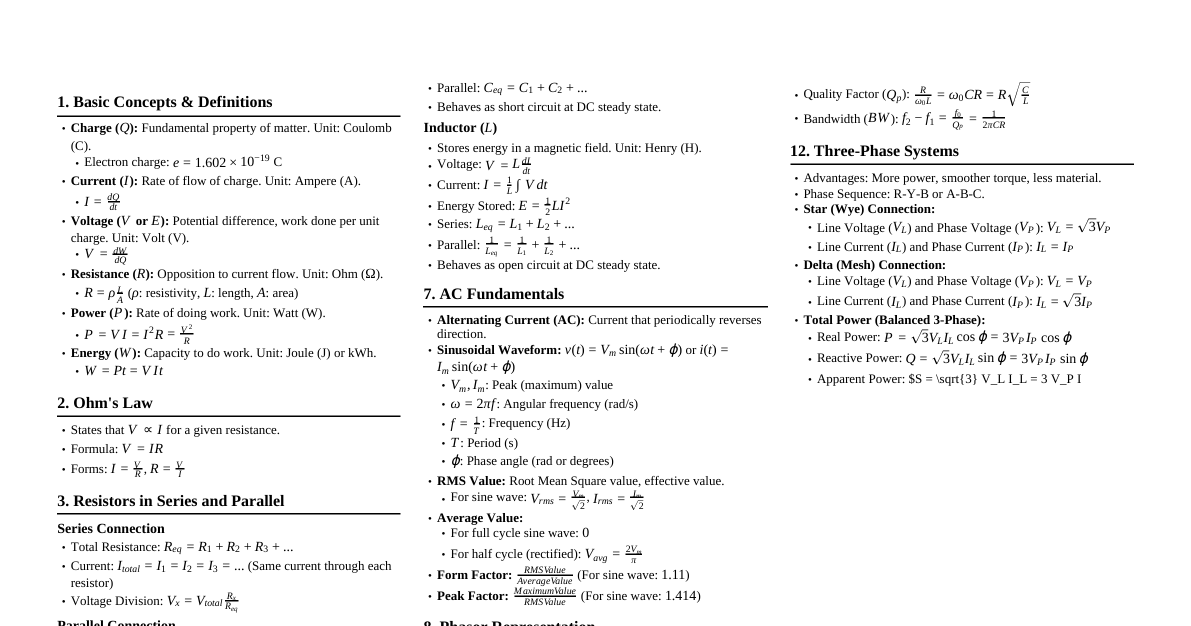
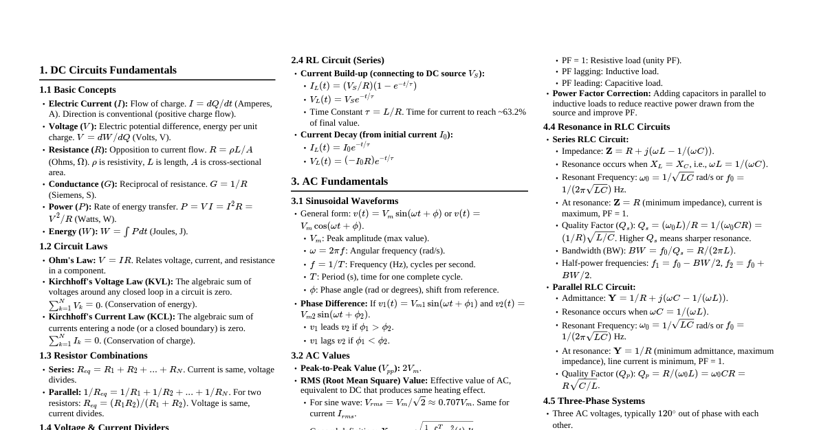
AC Circuits: Fundamentals Sinusoidal Waveforms: Instantaneous voltage: $v = V_m \sin(\omega t)$ or $v = V_m \sin(2\pi f t)$ $V_m$: peak applied voltage (V) $f$: supply frequency (Hz) $\omega = 2\pi f$: angular frequency (rad/s) $t$: time (s) Peak Value ($V_m$ or $I_m$): Maximum value attained during one cycle (amplitude/crest value). Cycle: One complete set of positive and negative values of an alternating quantity. Time Period ($T$): Time taken to complete one cycle ($T = 1/f$). Frequency ($f$): Number of cycles per second (Hz). Phase: The angular position of a waveform at a given instant. Phase Difference ($\phi$): Angular difference between two waveforms of the same frequency. Leading: Waveform A reaches its peak before Waveform B. Lagging: Waveform A reaches its peak after Waveform B. RMS Value (Root Mean Square): Effective value of an AC quantity. For sinusoidal voltage: $V_{rms} = \frac{V_m}{\sqrt{2}} \approx 0.707 V_m$ For sinusoidal current: $I_{rms} = \frac{I_m}{\sqrt{2}} \approx 0.707 I_m$ Power calculation uses RMS values: $P = V_{rms} I_{rms} \cos \phi$ Average Value: Average of all instantaneous values over one half-cycle. For sinusoidal voltage (half-cycle): $V_{avg} = \frac{2V_m}{\pi} \approx 0.637 V_m$ For sinusoidal current (half-cycle): $I_{avg} = \frac{2I_m}{\pi} \approx 0.637 I_m$ Over a full cycle, average value of a pure sine wave is zero. Form Factor ($K_f$): Ratio of RMS value to Average value. For sine wave: $K_f = \frac{V_{rms}}{V_{avg}} = \frac{V_m/\sqrt{2}}{2V_m/\pi} = \frac{\pi}{2\sqrt{2}} \approx 1.11$ Peak Factor (Crest Factor) ($K_p$): Ratio of Peak value to RMS value. For sine wave: $K_p = \frac{V_m}{V_{rms}} = \frac{V_m}{V_m/\sqrt{2}} = \sqrt{2} \approx 1.414$ Phasor Representation: A rotating vector representing a sinusoidal quantity. Length represents magnitude (RMS or peak). Angle represents phase relative to a reference. $V = V_{rms} \angle \theta$ AC Circuits: Basic Components 1. Pure Resistive AC Circuit (R) Circuit contains only resistance $R$. Voltage and Current: In phase. $\phi = 0^\circ$. $v = V_m \sin(\omega t)$ $i = I_m \sin(\omega t)$ where $I_m = V_m/R$ Impedance: $Z = R \angle 0^\circ = R$ Power: Instantaneous Power: $p = vi = V_m I_m \sin^2(\omega t) = P_{max} \frac{1-\cos(2\omega t)}{2}$ Average Power (Real Power): $P = V_{rms} I_{rms} = I_{rms}^2 R = \frac{V_{rms}^2}{R}$ Power Factor: $\cos \phi = \cos 0^\circ = 1$ 2. Pure Inductive AC Circuit (L) Circuit contains only inductance $L$. Voltage and Current: Current lags voltage by $90^\circ$. $v = V_m \sin(\omega t)$, $i = I_m \sin(\omega t - 90^\circ)$ Inductive Reactance ($X_L$): Opposition to AC current by an inductor. $X_L = \omega L = 2\pi f L$ (Ohms) $I_m = V_m/X_L$ Impedance: $Z = X_L \angle 90^\circ = j X_L$ Power: Real Power: $P = 0$ (ideal inductor consumes no real power) Reactive Power ($Q_L$): $Q_L = V_{rms} I_{rms} = I_{rms}^2 X_L = \frac{V_{rms}^2}{X_L}$ (VAR) Power Factor: $\cos \phi = \cos 90^\circ = 0$ (lagging) 3. Pure Capacitive AC Circuit (C) Circuit contains only capacitance $C$. Voltage and Current: Current leads voltage by $90^\circ$. $v = V_m \sin(\omega t)$, $i = I_m \sin(\omega t + 90^\circ)$ Capacitive Reactance ($X_C$): Opposition to AC current by a capacitor. $X_C = \frac{1}{\omega C} = \frac{1}{2\pi f C}$ (Ohms) $I_m = V_m/X_C$ Impedance: $Z = X_C \angle -90^\circ = -j X_C$ Power: Real Power: $P = 0$ (ideal capacitor consumes no real power) Reactive Power ($Q_C$): $Q_C = -V_{rms} I_{rms} = -I_{rms}^2 X_C = -\frac{V_{rms}^2}{X_C}$ (VAR) Power Factor: $\cos \phi = \cos(-90^\circ) = 0$ (leading) AC Circuits: Series Combinations 1. RL Series Circuit Resistance $R$ and Inductance $L$ in series. Impedance ($Z$): $Z = R + j X_L = \sqrt{R^2 + X_L^2} \angle \phi$ Magnitude: $|Z| = \sqrt{R^2 + X_L^2}$ Phase angle: $\phi = \arctan(X_L/R)$ (current lags voltage) Voltage Relationship: $\vec{V} = \vec{V_R} + \vec{V_L}$ (phasor sum) $V = \sqrt{V_R^2 + V_L^2}$ $V_R = I R$, $V_L = I X_L$ Power Factor: $\cos \phi = \frac{R}{|Z|} = \frac{V_R}{V}$ (lagging) Power: Real Power: $P = V I \cos \phi = I^2 R$ Reactive Power: $Q = V I \sin \phi = I^2 X_L$ Apparent Power: $S = V I = I^2 |Z| = \sqrt{P^2 + Q^2}$ (VA) 2. RC Series Circuit Resistance $R$ and Capacitance $C$ in series. Impedance ($Z$): $Z = R - j X_C = \sqrt{R^2 + X_C^2} \angle -\phi$ Magnitude: $|Z| = \sqrt{R^2 + X_C^2}$ Phase angle: $\phi = \arctan(X_C/R)$ (current leads voltage) Voltage Relationship: $\vec{V} = \vec{V_R} + \vec{V_C}$ (phasor sum) $V = \sqrt{V_R^2 + V_C^2}$ $V_R = I R$, $V_C = I X_C$ Power Factor: $\cos \phi = \frac{R}{|Z|} = \frac{V_R}{V}$ (leading) Power: Real Power: $P = V I \cos \phi = I^2 R$ Reactive Power: $Q = -V I \sin \phi = -I^2 X_C$ Apparent Power: $S = V I = I^2 |Z| = \sqrt{P^2 + Q^2}$ (VA) 3. RLC Series Circuit Resistance $R$, Inductance $L$, and Capacitance $C$ in series. Impedance ($Z$): $Z = R + j(X_L - X_C) = \sqrt{R^2 + (X_L - X_C)^2} \angle \phi$ Magnitude: $|Z| = \sqrt{R^2 + (X_L - X_C)^2}$ Phase angle: $\phi = \arctan\left(\frac{X_L - X_C}{R}\right)$ If $X_L > X_C$: inductive circuit, current lags. If $X_C > X_L$: capacitive circuit, current leads. If $X_L = X_C$: purely resistive circuit, current in phase (resonance). Voltage Relationship: $\vec{V} = \vec{V_R} + \vec{V_L} + \vec{V_C}$ (phasor sum) $V = \sqrt{V_R^2 + (V_L - V_C)^2}$ Power Factor: $\cos \phi = \frac{R}{|Z|}$ Series Resonance Occurs in an RLC series circuit when $X_L = X_C$. Resonant Frequency ($f_r$): $2\pi f_r L = \frac{1}{2\pi f_r C}$ $f_r = \frac{1}{2\pi \sqrt{LC}}$ (Hz) At Resonance: Impedance: $Z = R$ (minimum impedance, purely resistive) Current: $I = V/R$ (maximum current) Phase angle: $\phi = 0^\circ$ Power factor: $\cos \phi = 1$ (unity) $V_L = V_C$ (voltages across L and C are equal in magnitude and $180^\circ$ out of phase, canceling each other) Circuit behaves like a purely resistive circuit. Quality Factor (Q-factor): Measure of sharpness of resonance. $Q = \frac{X_L}{R} = \frac{X_C}{R} = \frac{\omega_r L}{R} = \frac{1}{\omega_r C R}$ $Q = \frac{1}{R}\sqrt{\frac{L}{C}}$ Higher Q means sharper resonance, higher voltage magnification across L and C. Bandwidth (BW): Range of frequencies for which power is at least half of the maximum power (half-power frequencies $f_1, f_2$). $BW = f_2 - f_1 = \frac{f_r}{Q} = \frac{R}{2\pi L}$ Selectivity: Ability of a resonant circuit to discriminate between frequencies. Higher Q means better selectivity. AC Circuits: Parallel Combinations (Overview) For parallel circuits, it's often easier to work with admittance ($Y$) instead of impedance ($Z$). Admittance: $Y = 1/Z = G + jB$ Conductance ($G$): $1/R$ (for resistance) Susceptance ($B$): $1/X_L$ or $1/X_C$ $B_L = -1/X_L = -1/(\omega L)$ $B_C = 1/X_C = \omega C$ Total Admittance: $Y_{total} = Y_1 + Y_2 + \dots$ Total Current: $\vec{I} = \vec{I_1} + \vec{I_2} + \dots$ (phasor sum) Parallel Resonance (RLC Parallel Circuit) Occurs when the reactive component of the total current is zero, meaning the applied voltage and total current are in phase. This implies $B_L = B_C$ (if parallel RLC) or the net susceptance is zero. For a parallel RLC circuit, $Y = \frac{1}{R} + j(\omega C - \frac{1}{\omega L})$. Resonance occurs when $\omega C - \frac{1}{\omega L} = 0$. Resonant Frequency ($f_r$): $\omega_r C = \frac{1}{\omega_r L} \implies \omega_r^2 = \frac{1}{LC}$ $f_r = \frac{1}{2\pi \sqrt{LC}}$ (Hz) - same as series resonance for ideal RLC. If R is present in L branch: $f_r = \frac{1}{2\pi} \sqrt{\frac{1}{LC} - \frac{R^2}{L^2}}$ At Resonance: Admittance: $Y = 1/R$ (minimum admittance, purely resistive) Impedance: $Z = R$ (maximum impedance) Current: $I = V/R$ (minimum current drawn from source) Phase angle: $\phi = 0^\circ$ Power factor: $\cos \phi = 1$ (unity) The circulating current between L and C can be very high. Conclusions for Parallel Resonance: $|Z_r|$ is very high (ideally infinite for R = 0). Circuit current $I_r = V/|Z_r|$ is very small. Often called a "Rejector Circuit" because it offers high impedance to the resonant frequency. Power in AC Circuits Real Power (P) / Active Power / Average Power: Unit: Watts (W) Power actually consumed by the circuit (converted to heat, work, etc.). $P = V_{rms} I_{rms} \cos \phi = I_{rms}^2 R = \frac{V_{rms}^2}{R}$ Reactive Power (Q): Unit: Volt-Ampere Reactive (VAR) Power exchanged between the source and reactive components (L, C). Not consumed. $Q = V_{rms} I_{rms} \sin \phi = I_{rms}^2 X = \frac{V_{rms}^2}{X}$ $Q_L$ is positive (inductive, lagging). $Q_C$ is negative (capacitive, leading). Apparent Power (S): Unit: Volt-Ampere (VA) Total power delivered by the source. $S = V_{rms} I_{rms} = \sqrt{P^2 + Q^2}$ $S = |Z| I_{rms}^2 = \frac{V_{rms}^2}{|Z|}$ Power Triangle: Hypotenuse: $S$ Adjacent side: $P$ Opposite side: $Q$ Angle between $S$ and $P$ is $\phi$. Power Factor (PF): $\text{PF} = \cos \phi = \frac{P}{S}$ Ranges from 0 to 1. Lagging PF: current lags voltage (inductive load). Leading PF: current leads voltage (capacitive load). Unity PF: current and voltage are in phase (resistive load, resonance). Three-Phase Balanced Circuits Consists of three AC voltages/currents shifted by $120^\circ$ from each other. Commonly generated by alternators. Advantages: More power, smoother power delivery, self-starting motors, less conductor material. Phase Sequence: Order in which phase voltages reach their maximum values (e.g., R-Y-B or A-B-C). Types of Connections: Star (Wye) Connection ($\mathbf{Y}$): Three phase windings connected at a common point called neutral. Line Voltage ($V_L$): Voltage between any two lines. Phase Voltage ($V_P$): Voltage between a line and neutral. Line Current ($I_L$): Current flowing in the line. Phase Current ($I_P$): Current flowing in each phase winding. Relationships: $V_L = \sqrt{3} V_P$ $I_L = I_P$ Delta (Mesh) Connection ($\mathbf{\Delta}$): Three phase windings connected end-to-end to form a closed loop. No neutral point. Relationships: $V_L = V_P$ $I_L = \sqrt{3} I_P$ Power in Three-Phase Circuits (Balanced Load): Total Real Power: $P_{total} = 3 V_P I_P \cos \phi = \sqrt{3} V_L I_L \cos \phi$ Total Reactive Power: $Q_{total} = 3 V_P I_P \sin \phi = \sqrt{3} V_L I_L \sin \phi$ Total Apparent Power: $S_{total} = 3 V_P I_P = \sqrt{3} V_L I_L$ $\phi$ is the phase angle between phase voltage and phase current.