Electric Circuit Analysis (Sadiku)
Cheatsheet Content
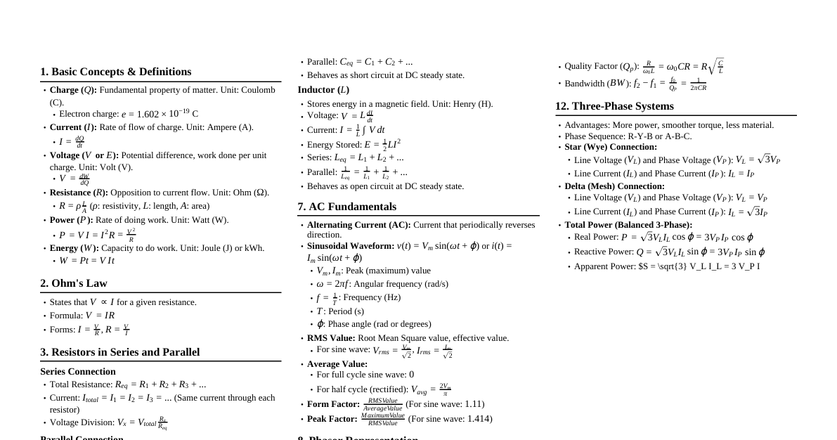
1. Basic Concepts & Definitions Charge ($q$): Measured in Coulombs (C). $1 \text{ C} = 6.24 \times 10^{18}$ electrons. Current ($i$): Rate of charge flow. $i = \frac{dq}{dt}$ (Amperes, A). DC: Constant current. AC: Time-varying current (e.g., sinusoidal). Voltage ($v$): Energy required to move a unit charge. $v = \frac{dw}{dq}$ (Volts, V). Potential difference. Power ($p$): Rate of energy transfer. $p = \frac{dw}{dt} = vi$ (Watts, W). Passive Sign Convention: If current enters the positive terminal, $p > 0$ (absorbed power), $p Energy ($w$): $w = \int p \, dt$ (Joules, J). Circuit Elements: Active: Supply energy (e.g., voltage source, current source). Passive: Absorb energy (e.g., resistor, inductor, capacitor). 2. Ohm's Law & Resistors Ohm's Law: $v = iR$ or $i = \frac{v}{R}$ or $R = \frac{v}{i}$. $R$: Resistance in Ohms ($\Omega$). Conductance ($G$): $G = \frac{1}{R}$ (Siemens, S or mhos). $i = Gv$. Power in a Resistor: $p = vi = i^2R = \frac{v^2}{R}$. Always absorbed. 3. Kirchhoff's Laws Kirchhoff's Current Law (KCL): Sum of currents entering a node is zero (or sum entering equals sum leaving). $\sum_{n=1}^N i_n = 0$. Kirchhoff's Voltage Law (KVL): Sum of voltages around any closed loop is zero. $\sum_{m=1}^M v_m = 0$. 4. Series & Parallel Resistors Series: $R_{eq} = R_1 + R_2 + \dots + R_N$. (Current is same, voltage divides) Parallel: $\frac{1}{R_{eq}} = \frac{1}{R_1} + \frac{1}{R_2} + \dots + \frac{1}{R_N}$. For two resistors: $R_{eq} = \frac{R_1R_2}{R_1+R_2}$. (Voltage is same, current divides) Current Divider: For two parallel resistors $R_1, R_2$, current $i_x$ through $R_x$: $i_1 = i_{total} \frac{R_2}{R_1+R_2}$, $i_2 = i_{total} \frac{R_1}{R_1+R_2}$. Voltage Divider: For two series resistors $R_1, R_2$, voltage $v_x$ across $R_x$: $v_1 = v_{total} \frac{R_1}{R_1+R_2}$, $v_2 = v_{total} \frac{R_2}{R_1+R_2}$. 5. Nodal & Mesh Analysis Nodal Analysis: Choose a reference node (ground, 0V). Assign node voltages to other $N-1$ non-reference nodes. Apply KCL at each non-reference node. Express currents using Ohm's Law ($i = (v_{node} - v_{neighbor})/R$). Solve the resulting system of equations for node voltages. Supernode: Formed by two non-reference nodes connected by a voltage source (or a voltage source and a resistor). Apply KCL to the combined supernode, and an additional constraint equation relating the two node voltages. Mesh Analysis: (Planar circuits only) Assign mesh currents $i_1, i_2, \dots, i_M$ to the $M$ meshes. Apply KVL to each mesh. Express voltages using Ohm's Law ($v = iR$). Solve the resulting system of equations for mesh currents. Supermesh: Formed by two meshes sharing a current source. Apply KVL to the combined supermesh, and an additional constraint equation relating the two mesh currents. 6. Circuit Theorems Linearity & Superposition: Linearity: Output is proportional to input. $f(ax_1 + bx_2) = af(x_1) + bf(x_2)$. Superposition: In a linear circuit with multiple independent sources, the total response is the sum of responses due to each independent source acting alone (turn off other independent sources: voltage sources to short, current sources to open). Source Transformation: Convert between voltage source in series with resistor and current source in parallel with resistor. Voltage source $V_s$ in series with $R \iff$ Current source $I_s = V_s/R$ in parallel with $R$. Thevenin's Theorem: Any linear two-terminal circuit can be replaced by an equivalent circuit consisting of a voltage source $V_{Th}$ in series with a resistor $R_{Th}$. $V_{Th}$: Open-circuit voltage at the terminals. $R_{Th}$: Equivalent resistance looking into the terminals with all independent sources turned off (dependent sources remain active). If dependent sources are present, apply a test source ($V_0$ or $I_0$) and find $R_{Th} = V_0/I_0$. Norton's Theorem: Any linear two-terminal circuit can be replaced by an equivalent circuit consisting of a current source $I_N$ in parallel with a resistor $R_N$. $I_N$: Short-circuit current at the terminals. $R_N$: Same as $R_{Th}$. $R_N = R_{Th} = V_{Th}/I_N$. Maximum Power Transfer: A load resistor $R_L$ receives maximum power from a circuit when $R_L = R_{Th}$. Maximum Power: $P_{max} = \frac{V_{Th}^2}{4R_{Th}}$. 7. Inductors & Capacitors (First-Order Circuits) Capacitor ($C$): Stores energy in an electric field. Measured in Farads (F). $q = Cv$ $i = C \frac{dv}{dt}$ $v(t) = \frac{1}{C} \int_{t_0}^t i(\tau) d\tau + v(t_0)$ Energy stored: $W_C = \frac{1}{2}Cv^2$ Does not allow instantaneous voltage change. Acts as open circuit in DC steady state. Inductor ($L$): Stores energy in a magnetic field. Measured in Henrys (H). $\phi = Li$ ($\phi$ is flux linkage) $v = L \frac{di}{dt}$ $i(t) = \frac{1}{L} \int_{t_0}^t v(\tau) d\tau + i(t_0)$ Energy stored: $W_L = \frac{1}{2}Li^2$ Does not allow instantaneous current change. Acts as short circuit in DC steady state. First-Order RC/RL Circuits (Source-Free): General form: $x(t) = x(0) e^{-t/\tau}$ RC Circuit (voltage): $v(t) = v(0) e^{-t/RC}$, $\tau = RC$ (time constant) RL Circuit (current): $i(t) = i(0) e^{-tL/R}$, $\tau = L/R$ (time constant) First-Order RC/RL Circuits (Step Response): General form: $x(t) = x(\infty) + [x(0) - x(\infty)]e^{-t/\tau}$ for $t \ge 0$. $x(0)$: Initial value. $x(\infty)$: Final value (steady state). $\tau$: Time constant. 8. Sinusoidal Steady-State Analysis (Phasors) Sinusoid: $v(t) = V_m \cos(\omega t + \phi)$. $V_m$: Amplitude. $\omega$: Angular frequency (rad/s). $\omega = 2\pi f$. $f$: Frequency (Hz). $f = 1/T$. $\phi$: Phase angle. Phasor: A complex number representing the amplitude and phase of a sinusoid. $V = V_m \angle \phi = V_m e^{j\phi} = V_m (\cos\phi + j\sin\phi)$. If $v(t) = V_m \sin(\omega t + \phi)$, convert to cosine: $v(t) = V_m \cos(\omega t + \phi - 90^\circ)$. Derivatives/Integrals in Phasor Domain: $j\omega X$ for $\frac{dX}{dt}$ $\frac{1}{j\omega} X$ for $\int X \, dt$ Impedance ($Z$): Generalized resistance for AC circuits. $Z = \frac{V}{I}$ (Ohms). Resistor: $Z_R = R$ Inductor: $Z_L = j\omega L$ Capacitor: $Z_C = \frac{1}{j\omega C} = -\frac{j}{\omega C}$ Admittance ($Y$): $Y = \frac{1}{Z}$ (Siemens). Resistor: $Y_R = G = \frac{1}{R}$ Inductor: $Y_L = \frac{1}{j\omega L} = -\frac{j}{\omega L}$ Capacitor: $Y_C = j\omega C$ Series/Parallel Impedances: Same rules as resistors. Series: $Z_{eq} = Z_1 + Z_2 + \dots$ Parallel: $\frac{1}{Z_{eq}} = \frac{1}{Z_1} + \frac{1}{Z_2} + \dots$ Nodal/Mesh Analysis with Phasors: Apply KCL/KVL using phasors and impedances. 9. AC Power Analysis Instantaneous Power: $p(t) = v(t)i(t)$. Average Power ($P$): $P = \frac{1}{T} \int_0^T p(t) dt = \frac{1}{2} V_m I_m \cos(\theta_v - \theta_i) = V_{rms} I_{rms} \cos(\theta_v - \theta_i)$ (Watts). RMS Value: For a sinusoid $X_m \cos(\omega t + \phi)$, $X_{rms} = \frac{X_m}{\sqrt{2}}$. $P = I_{rms}^2 R = \frac{V_{rms}^2}{R}$. Reactive Power ($Q$): Energy oscillating between source and reactive load. $Q = \frac{1}{2} V_m I_m \sin(\theta_v - \theta_i) = V_{rms} I_{rms} \sin(\theta_v - \theta_i)$ (VAR). $Q > 0$: Inductive load. $Q Complex Power ($S$): $S = P + jQ = V_{rms} I_{rms}^* = I_{rms}^2 Z = \frac{V_{rms}^2}{Z^*}$. $S = V I^*$ (where $V$ and $I$ are RMS phasors). Magnitude $|S|$ is Apparent Power (VA). Power Factor (PF): $\text{PF} = \cos(\theta_v - \theta_i) = \frac{P}{|S|}$. Lagging PF: Inductive load ($\theta_v > \theta_i$). Leading PF: Capacitive load ($\theta_v Power Factor Correction: Adding parallel capacitors/inductors to make PF closer to 1. 10. Frequency Response & Filters (Second-Order Circuits) Transfer Function ($H(\omega)$ or $H(s)$): Ratio of output phasor to input phasor. $H(\omega) = \frac{V_{out}(\omega)}{V_{in}(\omega)}$ or $\frac{I_{out}(\omega)}{I_{in}(\omega)}$. Bode Plots: Log-log plots of magnitude $|H(\omega)|$ and phase $\angle H(\omega)$ vs. $\omega$. Resonance: Occurs in RLC circuits when $X_L = X_C$, so $Z = R$. Resonant frequency: $\omega_0 = \frac{1}{\sqrt{LC}}$. Series RLC: $Z = R + j(\omega L - \frac{1}{\omega C})$. At resonance, $Z = R$. Parallel RLC: $Y = \frac{1}{R} + j(\omega C - \frac{1}{\omega L})$. At resonance, $Y = 1/R$. Bandwidth ($B$): Range of frequencies where power is at least half of maximum (or voltage is $1/\sqrt{2}$ of maximum). $B = \omega_2 - \omega_1$. Half-Power Frequencies ($\omega_1, \omega_2$): Frequencies where $|H(\omega)| = \frac{1}{\sqrt{2}} |H|_{max}$. Quality Factor ($Q$): Measure of sharpness of resonance. Series RLC: $Q = \frac{\omega_0 L}{R} = \frac{1}{\omega_0 RC}$. Parallel RLC: $Q = \frac{R}{\omega_0 L} = \omega_0 RC$. Also $Q = \frac{\omega_0}{B}$. Filter Types: Low-pass: Passes low frequencies, attenuates high. High-pass: Passes high frequencies, attenuates low. Band-pass: Passes a band of frequencies. Band-stop: Attenuates a band of frequencies.