Ray Optics & Optical Instruments
Cheatsheet Content
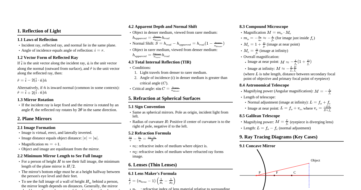
1. Introduction to Ray Optics Light: Electromagnetic waves (400 nm to 750 nm wavelength) detected by the human eye. Properties: Travels with enormous speed ($c \approx 3 \times 10^8 \, m/s$ in vacuum). Travels in a straight line (ray of light). Ray: Path of light. Beam: A bundle of rays. Key Phenomena: Reflection, refraction, dispersion. 2. Reflection by Spherical Mirrors 2.1 Laws of Reflection Angle of incidence ($i$) = Angle of reflection ($r$). Incident ray, reflected ray, and normal lie in the same plane. These laws apply to all reflecting surfaces, including curved ones. 2.2 Sign Convention (Cartesian) Distances measured from pole/optical center. Distances in direction of incident light are positive. Distances opposite to incident light are negative. Heights upwards (normal to x-axis) are positive. Heights downwards are negative. 2.3 Focal Length of Spherical Mirrors Principal Focus (F): Point where paraxial rays converge (concave) or appear to diverge (convex) after reflection. Focal Plane: Plane through F normal to the principal axis. Focal Length ($f$): Distance from pole (P) to focus (F). Relation: $f = R/2$, where $R$ is the radius of curvature. Concave mirror: $f$ is negative. Convex mirror: $f$ is positive. 2.4 Image Formation (Mirror Equation) Image: Point where rays actually meet (real) or appear to diverge from (virtual). Mirror Equation: $\frac{1}{v} + \frac{1}{u} = \frac{1}{f}$ $u$: object distance (negative for real objects). $v$: image distance (positive for real images, negative for virtual images). $f$: focal length. Linear Magnification ($m$): $m = \frac{h'}{h} = -\frac{v}{u}$ $h'$: height of image, $h$: height of object. $m > 0$: erect and virtual image. $m 2.5 Ray Tracing Rules for Spherical Mirrors Ray parallel to principal axis passes through F (or appears to). Ray passing through C (or appearing to) retraces its path. Ray passing through F (or directed towards) becomes parallel to principal axis. Ray incident at pole reflects such that angle of incidence = angle of reflection. 3. Refraction of Light Definition: Change in direction of light as it enters a new transparent medium. Laws of Refraction (Snell's Law): Incident ray, refracted ray, and normal lie in the same plane. $\frac{\sin i}{\sin r} = n_{21}$ (constant), where $n_{21}$ is the refractive index of medium 2 with respect to medium 1. Refractive Index: $n_{21} = \frac{n_2}{n_1} = \frac{c_1}{c_2}$ (ratio of speed of light in medium 1 to medium 2). Optical Density: $n_{21} > 1 \implies r $n_{21} i$: light bends away from normal (medium 2 is optically rarer). Relation between $n_{12}$ and $n_{21}$: $n_{12} = \frac{1}{n_{21}}$. Apparent Depth: For normal viewing, $h_{apparent} = \frac{h_{real}}{n}$. 4. Total Internal Reflection (TIR) Occurs when light travels from a denser to a rarer medium. Angle of incidence ($i$) must be greater than critical angle ($i_c$). Critical Angle: Angle of incidence for which angle of refraction is $90^\circ$. $\sin i_c = n_{21}$ (where $n_{21}$ is refractive index of rarer medium with respect to denser medium). Applications: Prisms (90°, 180° bends), optical fibers, mirage. Optical Fibers: Core (higher $n$) and cladding (lower $n$). Light undergoes repeated TIR inside the core. 5. Refraction at Spherical Surfaces and Lenses 5.1 Refraction at a Single Spherical Surface Formula: $\frac{n_2}{v} - \frac{n_1}{u} = \frac{n_2 - n_1}{R}$ $n_1$: refractive index of medium where object is. $n_2$: refractive index of medium where image is formed. $u$: object distance, $v$: image distance, $R$: radius of curvature. 5.2 Lenses Lens Maker's Formula: $\frac{1}{f} = (n_2 - n_1) \left(\frac{1}{R_1} - \frac{1}{R_2}\right)$ (considering $n_1=1$ for air, $\frac{1}{f} = (n-1) \left(\frac{1}{R_1} - \frac{1}{R_2}\right)$) $f$: focal length, $n$: refractive index of lens material. $R_1, R_2$: radii of curvature of the two lens surfaces. Convex lens: positive $f$. Concave lens: negative $f$. Thin Lens Formula: $\frac{1}{v} - \frac{1}{u} = \frac{1}{f}$ Same sign convention as mirrors. Linear Magnification ($m$): $m = \frac{h'}{h} = \frac{v}{u}$ 5.3 Power of a Lens ($P$) Definition: Measure of convergence/divergence. $P = \frac{1}{f}$ (where $f$ is in meters). Unit: Dioptre (D). $1 \, D = 1 \, m^{-1}$. Converging lens ($f > 0$) has positive power. Diverging lens ($f 5.4 Combination of Thin Lenses in Contact Equivalent Focal Length: $\frac{1}{F} = \frac{1}{f_1} + \frac{1}{f_2} + \frac{1}{f_3} + \dots$ Total Power: $P = P_1 + P_2 + P_3 + \dots$ Total Magnification: $m = m_1 \times m_2 \times m_3 \times \dots$ 6. Refraction through a Prism Angle of Deviation ($\delta$): The angle by which the emergent ray deviates from the incident ray. $\delta = (i + e) - A$ $A = r_1 + r_2$ $i$: angle of incidence, $e$: angle of emergence, $A$: angle of prism. $r_1, r_2$: angles of refraction inside the prism. Minimum Deviation ($D_m$): Occurs when $i = e$ and $r_1 = r_2 = A/2$. Refractive index of prism material: $n = \frac{\sin[(A+D_m)/2]}{\sin(A/2)}$ For small angle prism: $D_m = (n-1)A$. 7. Optical Instruments 7.1 Simple Microscope (Magnifying Glass) Converging lens of small focal length. Object placed within focal length for virtual, erect, magnified image. Angular Magnification: Image at near point (D = 25 cm): $m = 1 + \frac{D}{f}$ Image at infinity (relaxed eye): $m = \frac{D}{f}$ 7.2 Compound Microscope Two lenses: Objective (short $f_o$, short aperture) and Eyepiece (short $f_e$, large aperture). Objective forms real, inverted, magnified image ($I_1$). Eyepiece acts as simple microscope to magnify $I_1$ into final virtual, inverted image. Total Magnification: $m = m_o \times m_e = \frac{L}{f_o} \times (1 + \frac{D}{f_e})$ (image at near point). $L$: tube length (distance between second focal point of objective and first focal point of eyepiece). For image at infinity: $m = \frac{L}{f_o} \times \frac{D}{f_e}$. 7.3 Telescope (Refracting) Two lenses: Objective (long $f_o$, large aperture) and Eyepiece (short $f_e$, small aperture). Objective forms real, inverted image of distant object at its focal plane. Eyepiece magnifies this image. Magnifying Power: $m = \frac{f_o}{f_e}$ (for image at infinity/normal adjustment). Length of Telescope Tube: $L = f_o + f_e$. 7.4 Reflecting Telescopes Use concave mirror as objective. Advantages: No chromatic aberration, easier mechanical support for large apertures. Example: Cassegrain telescope.