Inorganic Chemistry Review
Cheatsheet Content
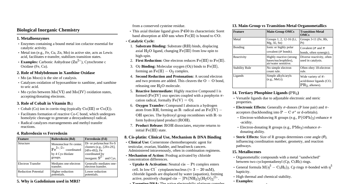
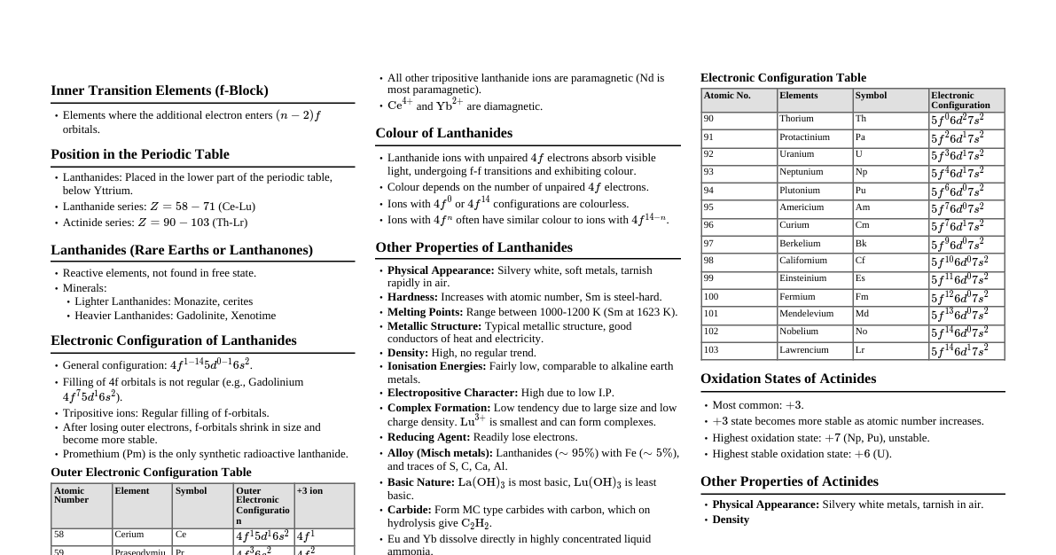
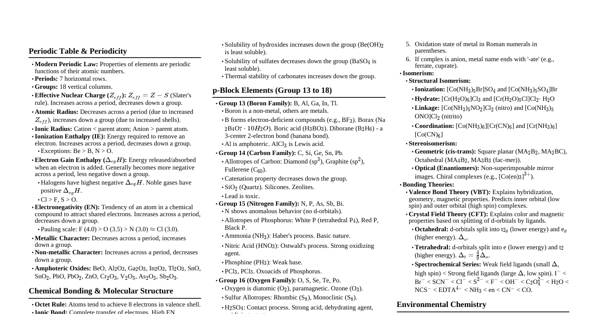
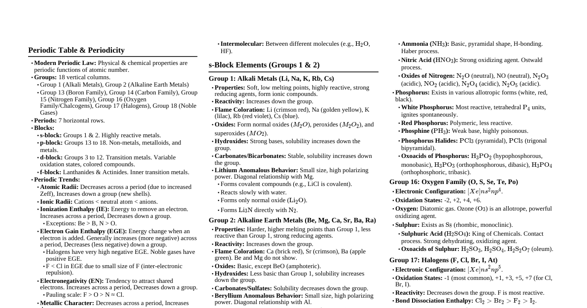
### Q1) Linear Combination of Atomic Orbitals (LCAO) The Linear Combination of Atomic Orbitals (LCAO) method is a quantum superposition of atomic orbitals and is a technique for calculating molecular orbitals in quantum chemistry. It provides an approximate description of the molecular orbitals of a molecule. #### Principles: 1. **Overlap:** Atomic orbitals must overlap significantly for effective combination. 2. **Symmetry:** Atomic orbitals must have compatible symmetry with respect to the internuclear axis. 3. **Energy:** Atomic orbitals must be of comparable energy. #### Process: When two atomic orbitals (e.g., $\psi_A$ and $\psi_B$) combine, they can do so in two ways: 1. **Constructive Interference (Addition):** If the wave functions add in phase, a **bonding molecular orbital** ($\sigma$ or $\pi$) is formed. This orbital has increased electron density between the nuclei, leading to attraction and lower energy. $$\Psi_{bonding} = c_1\psi_A + c_2\psi_B$$ 2. **Destructive Interference (Subtraction):** If the wave functions subtract (are out of phase), an **antibonding molecular orbital** ($\sigma^*$ or $\pi^*$) is formed. This orbital has a nodal plane between the nuclei, decreased electron density, and higher energy. $$\Psi_{antibonding} = c_1\psi_A - c_2\psi_B$$ The coefficients $c_1$ and $c_2$ depend on the relative energies and overlap of the atomic orbitals. For homonuclear diatomics, $c_1 = c_2$. #### Example: H₂ Molecule Two 1s atomic orbitals combine to form one $\sigma_{1s}$ bonding MO and one $\sigma^*_{1s}$ antibonding MO. *(Self-correction: The prompt says "use these for " only if "user provided images/“Image URLs”". The URLs provided are for the question paper, not for diagrams. So I should not use the provided URLs for diagrams. I will revert to describing the diagram.)* *(Description of a typical LCAO diagram for H₂)* **Diagram:** Imagine two separate 1s atomic orbitals for two Hydrogen atoms on the left and right. In the center, an energy level diagram shows: - Below the energy of the 1s AOs, a $\sigma_{1s}$ molecular orbital. - Above the energy of the 1s AOs, a $\sigma^*_{1s}$ molecular orbital. Two electrons (one from each H atom) fill the lower energy $\sigma_{1s}$ MO, leading to bond formation. #### Significance: - Explains chemical bonding and molecular stability. - Predicts molecular properties like bond order, magnetic behavior, and electronic transitions. ### Q2) Shape of NH₃ and BF₃ using VSEPR Theory VSEPR (Valence Shell Electron Pair Repulsion) theory predicts the geometry of molecules based on minimizing electrostatic repulsion between electron pairs in the valence shell of the central atom. #### a) NH₃ (Ammonia) 1. **Central Atom:** Nitrogen (N) 2. **Valence Electrons of N:** 5 3. **Electrons from H atoms:** 3 (one from each H) 4. **Total Valence Electrons:** 5 + 3 = 8 5. **Number of Bond Pairs:** 3 (N-H bonds) 6. **Number of Lone Pairs:** $(8 - (3 \times 2)) / 2 = 1$ lone pair 7. **Total Electron Pairs:** 3 bond pairs + 1 lone pair = 4 electron pairs 8. **Electron Geometry:** Tetrahedral (due to 4 electron pairs) 9. **Molecular Geometry:** Trigonal Pyramidal. The lone pair occupies more space than bond pairs, repelling the N-H bond pairs and compressing the bond angles from the ideal $109.5^\circ$ to approximately $107^\circ$. **Diagram:** - Central N atom with three H atoms forming a pyramid base and the N at the apex. - A lone pair of electrons pointing away from the base, above the N atom. #### b) BF₃ (Boron Trifluoride) 1. **Central Atom:** Boron (B) 2. **Valence Electrons of B:** 3 3. **Electrons from F atoms:** 3 (one from each F) 4. **Total Valence Electrons:** 3 + 3 = 6 5. **Number of Bond Pairs:** 3 (B-F bonds) 6. **Number of Lone Pairs:** $(6 - (3 \times 2)) / 2 = 0$ lone pairs 7. **Total Electron Pairs:** 3 bond pairs + 0 lone pairs = 3 electron pairs 8. **Electron Geometry:** Trigonal Planar (due to 3 electron pairs) 9. **Molecular Geometry:** Trigonal Planar. All three B-F bonds lie in the same plane, with bond angles of $120^\circ$. **Diagram:** - Central B atom with three F atoms arranged symmetrically around it in a flat triangular shape. - No lone pairs shown on the B atom. ### Q3) Radius Ratio and its Significance #### Definition: The **radius ratio ($r_+/r_-$)** is the ratio of the radius of the cation ($r_+$) to the radius of the anion ($r_-$) in an ionic compound. $$ \text{Radius Ratio} = \frac{r_+}{r_-} $$ #### Significance: The radius ratio rule helps to predict the coordination number (CN) of the ions and the resulting crystal structure of ionic solids. It is based on the geometric principle that cations and anions in an ionic crystal try to maximize their contact while maintaining electrical neutrality. The stability of an ionic crystal depends on the cation being in contact with the maximum possible number of anions (high coordination number) without the anions touching each other. #### Radius Ratio Rules and Coordination Numbers: | Radius Ratio ($r_+/r_-$) | Coordination Number | Geometry | Example | | :------------------------ | :------------------ | :----------------- | :-------- | | 0.155 - 0.225 | 3 | Planar Trigonal | B₂O₃ | | 0.225 - 0.414 | 4 | Tetrahedral | ZnS (Zinc Blende) | | 0.414 - 0.732 | 6 | Octahedral | NaCl | | 0.732 - 1.000 | 8 | Cubic | CsCl | - **Prediction of Crystal Structure:** By calculating the radius ratio for a given ionic compound, one can predict its probable coordination number and hence its crystal lattice type (e.g., rock salt, cesium chloride, zinc blende). - **Stability:** A higher coordination number generally corresponds to a more stable structure, provided the anions do not overlap. The radius ratio helps determine the most stable geometric arrangement. - **Limitations:** It's a geometric rule and doesn't account for factors like covalent character, polarization, or non-spherical ions, which can lead to deviations from predictions. ### Q4) Lattice Energy: Formation and Significance #### Definition: **Lattice energy ($U$)** is the energy released when one mole of an ionic compound is formed from its constituent gaseous ions. Alternatively, it is the energy required to break one mole of an ionic solid into its constituent gaseous ions. It is usually expressed as a positive value for the dissociation process and a negative value for the formation process. For example, for NaCl: $$ \text{Na}^+(g) + \text{Cl}^-(g) \rightarrow \text{NaCl}(s) \quad \Delta H = -U $$ #### Formation (Born-Haber Cycle): Lattice energy cannot be measured directly but can be calculated using the Born-Haber cycle, which applies Hess's Law to relate lattice energy to other measurable thermodynamic quantities. For the formation of an ionic solid MX from its elements M(s) and X₂(g): $$ \text{M}(s) + \frac{1}{2}\text{X}_2(g) \rightarrow \text{MX}(s) \quad \Delta H_f^\circ $$ The Born-Haber cycle breaks this process into several steps: 1. **Sublimation of Metal (M(s) $\rightarrow$ M(g)):** $\Delta H_{sub}$ 2. **Ionization of Metal (M(g) $\rightarrow$ M$^+$(g) + e⁻):** Ionization Energy (IE) 3. **Dissociation of Non-metal (½X₂(g) $\rightarrow$ X(g)):** ½ Bond Dissociation Energy (BDE) 4. **Electron Affinity of Non-metal (X(g) + e⁻ $\rightarrow$ X⁻(g)):** Electron Affinity (EA) 5. **Formation of Ionic Solid (M$^+$(g) + X⁻(g) $\rightarrow$ MX(s)):** Lattice Energy ($U$) According to Hess's Law: $$ \Delta H_f^\circ = \Delta H_{sub} + \text{IE} + \frac{1}{2}\text{BDE} + \text{EA} + U $$ From this, lattice energy can be calculated: $$ U = \Delta H_f^\circ - (\Delta H_{sub} + \text{IE} + \frac{1}{2}\text{BDE} + \text{EA}) $$ **Diagram:** A Born-Haber cycle diagram for NaCl would show energy levels: - Elements (Na(s), ½Cl₂(g)) at a starting energy level. - Upward arrows for sublimation of Na, dissociation of Cl₂, ionization of Na, and electron affinity of Cl (if EA is positive, otherwise downward). - A final downward arrow from gaseous ions (Na⁺(g), Cl⁻(g)) to NaCl(s), representing the lattice energy. - The overall enthalpy of formation ($\Delta H_f^\circ$) connects the initial elements to the final solid. #### Significance: 1. **Stability of Ionic Compounds:** A larger (more negative) lattice energy indicates a stronger ionic bond and thus a more stable ionic compound. 2. **Solubility:** Compounds with very high lattice energies tend to be less soluble in polar solvents (like water) because the energy released upon solvation (hydration energy) is insufficient to overcome the lattice energy. 3. **Predicting Properties:** It helps to understand and predict properties like melting points (higher lattice energy usually means higher melting point) and hardness. 4. **Theoretical Calculations:** Lattice energy can also be estimated using theoretical models like the Born-Lande equation or Kapustinskii equation, providing insights into crystal structures and interionic forces. ### Q5) M-CO Bonding Modes in Metal Carbonyls Carbon monoxide (CO) is a versatile ligand in coordination chemistry, forming metal carbonyls with transition metals. It can bond to metals in various modes, primarily due to its ability to act as both a $\sigma$-donor and a $\pi$-acceptor (synergic bonding). #### Types of M-CO Bonding Modes: 1. **Terminal CO (μ₁-CO):** - In this most common mode, the CO molecule binds to a single metal atom through its carbon end. - The carbon atom donates a lone pair from its highest occupied molecular orbital (HOMO) to an empty d-orbital of the metal (M $\leftarrow$ CO $\sigma$-donation). - The metal then back-donates electron density from a filled d-orbital to the empty $\pi^*$ antibonding orbital of CO (M $\rightarrow$ CO $\pi$-back-donation). - **Structure:** M-C≡O - **IR Stretching Frequency:** Typically around $1850-2120 \text{ cm}^{-1}$. - **Diagram:** A metal atom (M) directly bonded to a carbon (C), which is triple-bonded to an oxygen (O). 2. **Bridging CO (μ-CO):** CO can bridge two or more metal atoms. This is common in polynuclear metal carbonyls. a. **Doubly Bridging (μ₂-CO):** - The CO molecule bridges two metal atoms. The carbon atom forms a bond with both metal atoms. - **Structure:** M-C-M (with O attached to C) - **IR Stretching Frequency:** Typically around $1700-1850 \text{ cm}^{-1}$. (Lower than terminal due to stronger M-C $\pi$-back-donation reducing C-O bond order). - **Diagram:** Two metal atoms (M) connected by a carbon atom (C) which is also bonded to an oxygen (O). The C-O bond appears more like a double bond. b. **Triply Bridging (μ₃-CO):** - The CO molecule bridges three metal atoms, often found in triangular metal clusters. - **Structure:** A carbon atom bonded to three metal atoms, with the oxygen atom bonded to the carbon. - **IR Stretching Frequency:** Typically around $1620-1700 \text{ cm}^{-1}$. (Even lower than μ₂-CO). - **Diagram:** Three metal atoms (M) forming a triangle. A carbon atom (C) is located above or below the center of this triangle, bonded to all three M atoms, and also to an oxygen (O). #### Other Less Common Modes: - **μ₄-CO:** Bridging four metal atoms (rare). - **Side-on bonding (η²-CO):** Where both carbon and oxygen atoms interact with a single metal, or bridging multiple metals. This is very rare for simple CO and generally involves highly electron-rich metal centers. #### Factors Affecting Bonding Mode: - **Electron Deficiency of Metal:** Electron-deficient metals tend to prefer bridging CO to achieve an 18-electron count. - **Steric Factors:** Bulky ligands might favor terminal CO. - **Metal Cluster Size:** Larger clusters can accommodate higher bridging modes. ### Q6) Method of Mixed Metal Cluster Synthesis Mixed-metal clusters contain two or more different metal atoms within the same cluster core. Their synthesis often involves strategies that allow for controlled incorporation of different metal fragments. #### Method: Building-Block Approach / Fragment Condensation This is a widely used and versatile method for synthesizing mixed-metal clusters. It involves preparing pre-formed metal fragments (building blocks) and then combining them under specific conditions. **General Strategy:** 1. **Preparation of Reactive Metal Fragments:** Create electron-deficient or coordinatively unsaturated metal complexes (building blocks) of one metal. These fragments often have labile ligands or available coordination sites. * **Example:** A carbonyl complex with easily removable ligands, or a metal hydride. 2. **Reaction with Another Metal Precursor:** React these fragments with a precursor of a different metal, which can itself be a fragment or a simple salt. The reaction typically involves: * **Ligand Substitution:** Labile ligands are replaced by the incoming metal fragment. * **Redox Reactions:** Electron transfer can facilitate bond formation. * **Condensation:** Formation of metal-metal bonds, often accompanied by the elimination of small molecules (e.g., H₂, CO, halides). **Example: Synthesis of a Mixed Ru-Os Carbonyl Cluster** Consider the synthesis of a di- or tri-nuclear cluster containing both Ruthenium (Ru) and Osmium (Os). **Step 1: Preparation of a Ruthenium Fragment (e.g., a hydrido carbonyl)** A common precursor is $\text{Ru}_3(\text{CO})_{12}$. It can be cleaved or reacted to form a more reactive fragment, e.g., by reaction with a base or upon photolysis. $$ \text{Ru}_3(\text{CO})_{12} \xrightarrow{\text{H}_2} \text{RuH}_2(\text{CO})_4 \quad \text{or similar reactive Ru fragment} $$ **Step 2: Reaction with an Osmium Precursor** A reactive osmium carbonyl precursor, such as $\text{Os}_3(\text{CO})_{12}$, can be used. Or, more simply, a suitable Osmium salt or another pre-formed Osmium fragment. Let's illustrate with a common example where a specific fragment is used to "grow" a cluster: Synthesis of $\text{H}_2\text{RuOs}_2(\text{CO})_{13}$ from $\text{Os}(\text{CO})_4(\text{H})_2$ and $\text{Ru}_3(\text{CO})_{12}$. $$ \text{Os}(\text{CO})_4(\text{H})_2 + \text{Ru}_3(\text{CO})_{12} \xrightarrow{\text{Heat}} \text{H}_2\text{RuOs}_2(\text{CO})_{13} + \text{other products} $$ A more controlled approach often involves a specific reactive fragment: 1. **Generate a suitable Ru fragment:** For instance, a coordinatively unsaturated $\text{Ru}(\text{CO})_4$ species (often generated *in situ*). 2. **React with an Osmium precursor:** $$ \text{Ru}(\text{CO})_4 + \text{Os}_3(\text{CO})_{12} \rightarrow \text{RuOs}_3(\text{CO})_{16} \quad (\text{if conditions allow for larger cluster}) $$ Or, for a dinuclear cluster: $$ \text{Ru}(\text{CO})_x + \text{Os}(\text{CO})_y \rightarrow \text{RuOs}(\text{CO})_z $$ This often involves the use of bridging ligands or controlled thermal/photochemical conditions to facilitate metal-metal bond formation. **Key Features of Building-Block Approach:** - **Control:** Allows for better control over the stoichiometry and nuclearity of the resulting mixed-metal cluster. - **Versatility:** Applicable to a wide range of metal combinations. - **Stepwise Assembly:** Complex clusters can be built up in a stepwise manner. **Other Methods (Briefly):** - **Co-condensation:** Simultaneous reduction of two different metal precursors. - **Ligand Exchange:** Replacing ligands in a homometallic cluster with ligands that favor interaction with a different metal. ### Q7) a) Resonance Hybrids; Stability of Carbonate and Nitrate Ions #### Resonance Hybrids: **Resonance** is a way of describing delocalized electrons within certain molecules or polyatomic ions where the bonding cannot be expressed by a single Lewis formula. A **resonance hybrid** is the actual structure of the molecule, which is an average of all possible contributing resonance structures (canonical forms). #### Characteristics of Resonance Hybrid: - It is more stable than any single contributing structure. - It cannot be represented by a single Lewis structure. - The delocalization of electrons results in lower energy and increased stability. - Bond lengths and angles in the hybrid are intermediate between those predicted by individual resonance structures. #### Illustration of Stability via Resonance: **1. Carbonate Ion ($\text{CO}_3^{2-}$):** The carbonate ion has one central carbon atom bonded to three oxygen atoms, with a 2- charge. **Resonance Structures (Canonical Forms):** - Structure 1: C=O double bond, two C-O single bonds, two negative charges on the single-bonded oxygens. - Structure 2: C=O double bond rotated to another oxygen. - Structure 3: C=O double bond rotated to the third oxygen. **Diagram:** - Draw a central C atom. - First structure: Top O is double bonded to C, bottom-left O and bottom-right O are single bonded to C. Each single-bonded O has 3 lone pairs and a -1 charge. The double-bonded O has 2 lone pairs. - Second structure: Shift the double bond to the bottom-left O, and the single bonds to top O and bottom-right O. - Third structure: Shift the double bond to the bottom-right O, and the single bonds to top O and bottom-left O. - Use double-headed arrows between these structures. **Resonance Hybrid:** The actual carbonate ion is a trigonal planar structure where all three C-O bonds are equivalent and have a bond order of approximately 1.33 (one double bond shared among three positions). The 2- charge is delocalized over all three oxygen atoms. - **Stability:** The delocalization of the negative charge over multiple oxygen atoms reduces electron-electron repulsion and distributes the charge more evenly, making the carbonate ion significantly more stable than any single Lewis structure would suggest. **2. Nitrate Ion ($\text{NO}_3^{-}$):** The nitrate ion has one central nitrogen atom bonded to three oxygen atoms, with a 1- charge. **Resonance Structures (Canonical Forms):** - Structure 1: N=O double bond, two N-O single bonds, one negative charge on one single-bonded oxygen. - Structure 2: N=O double bond rotated to another oxygen. - Structure 3: N=O double bond rotated to the third oxygen. **Diagram:** - Draw a central N atom. - First structure: Top O is double bonded to N, bottom-left O and bottom-right O are single bonded to N. One single-bonded O has 3 lone pairs and a -1 charge, the other single-bonded O has 3 lone pairs and no formal charge (N has +1 formal charge). The double-bonded O has 2 lone pairs and no formal charge. - Second and Third structures: Rotate the double bond and negative charge similarly to the carbonate example. - Use double-headed arrows between these structures. **Resonance Hybrid:** The actual nitrate ion is a trigonal planar structure where all three N-O bonds are equivalent and have a bond order of approximately 1.33. The 1- charge is delocalized over all three oxygen atoms. - **Stability:** Similar to the carbonate ion, the delocalization of the negative charge and the $\pi$-electron density across the N-O bonds in the nitrate ion lowers its potential energy, making it more stable than any single contributing Lewis structure. ### Q7) b) Hybridization and Formation/Characteristics of dsp² Hybrid Orbitals #### Hybridization: **Hybridization** is the concept of mixing atomic orbitals of different energies (e.g., s, p, d) on a central atom to form new, degenerate hybrid orbitals that are suitable for the pairing of electrons to form chemical bonds. These hybrid orbitals have specific shapes, orientations, and energies that are intermediate between the original atomic orbitals, allowing for the formation of stronger and more stable bonds. #### dsp² Hybridization: **Formation:** dsp² hybridization involves the mixing of one (n-1)d orbital, one ns orbital, and two np orbitals (where n is the principal quantum number of the valence shell) to form four equivalent dsp² hybrid orbitals. This type of hybridization is typically observed in transition metal complexes, particularly those with a coordination number of four and a square planar geometry. **Steps for Formation (e.g., in [Ni(CN)₄]²⁻):** 1. **Ground State:** The central metal atom (e.g., Ni) has its electrons in its d, s, and p orbitals. For $\text{Ni}^{2+}$ (d⁸ configuration), in its isolated gaseous state, the electrons would fill the 3d orbitals (8 electrons), with 4s and 4p empty. 2. **Ligand Approach:** As strong field ligands (like CN⁻) approach the metal ion, they cause a large splitting of the d-orbitals. 3. **Electron Pairing:** Due to the strong ligand field, the 3d electrons pair up in the lower energy d-orbitals, leaving one 3d orbital (often the $d_{x^2-y^2}$) empty. * For Ni²⁺ (d⁸), the 8 electrons pair up in four 3d orbitals ($d_{xy}, d_{yz}, d_{xz}, d_{z^2}$), leaving the $d_{x^2-y^2}$ empty. 4. **Hybridization:** The empty 3d ($d_{x^2-y^2}$), one 4s, and two 4p ($p_x, p_y$) orbitals mix to form four equivalent dsp² hybrid orbitals. These hybrid orbitals point towards the corners of a square. 5. **Bonding:** Each of the four dsp² hybrid orbitals accepts a lone pair of electrons from a ligand (e.g., CN⁻) to form four metal-ligand $\sigma$ bonds. **Diagram:** - Show the atomic orbitals of the central metal (e.g., Ni²⁺): five 3d orbitals (four filled with paired electrons, one empty), one empty 4s, three empty 4p. - Show the hybridization process where one 3d, one 4s, and two 4p orbitals combine. - Show the resulting four dsp² hybrid orbitals, all at the same energy level, oriented in a square planar arrangement. - Show four ligands donating electron pairs into these hybrid orbitals. #### Characteristics of dsp² Hybrid Orbitals: 1. **Number and Equivalence:** Four dsp² hybrid orbitals are formed, which are degenerate (equal in energy) and equivalent in shape. 2. **Geometry:** They are directed towards the four corners of a square, resulting in a **square planar molecular geometry**. The bond angles are $90^\circ$. 3. **Bonding:** They are highly directional, leading to strong $\sigma$ bonds with incoming ligands. 4. **Magnetic Properties:** Since dsp² hybridization typically involves the pairing of d-electrons (due to strong field ligands), complexes exhibiting this hybridization are often **diamagnetic** (e.g., [Ni(CN)₄]²⁻). 5. **Inner-Orbital Complex:** Because an inner (n-1)d orbital is used for hybridization, these complexes are often referred to as "inner orbital complexes." 6. **Examples:** Common in d⁸ complexes of transition metals, such as $\text{Ni}^{2+}$ ([Ni(CN)₄]²⁻, [Ni(dmgH)₂]), $\text{Pd}^{2+}$, $\text{Pt}^{2+}$, and $\text{Au}^{3+}$. ### Q8) a) Necessary Conditions to Form Stable Ionic Compounds The formation of a stable ionic compound is favored by a combination of factors that maximize electrostatic attraction and minimize repulsion. 1. **Large Electronegativity Difference:** - Ionic bonds form between atoms with a significant difference in electronegativity (typically > 1.7 on the Pauling scale). - This allows for the complete transfer of electrons from the less electronegative atom (metal) to the more electronegative atom (non-metal), forming stable ions. - **Example:** In NaCl, Na ($EN \approx 0.93$) and Cl ($EN \approx 3.16$) have a large difference, facilitating electron transfer from Na to Cl to form $\text{Na}^+$ and $\text{Cl}^-$. 2. **Low Ionization Energy (for metal):** - Metals with low ionization energies readily lose valence electrons to form stable cations. - This process requires energy input, but a lower IE means less energy is needed, making the overall process more favorable. - **Example:** Alkali metals (Li, Na, K) have very low ionization energies, making them prone to forming +1 cations. 3. **High Electron Affinity (for non-metal):** - Non-metals with high electron affinities readily accept electrons to form stable anions. - This process often releases energy, contributing to the overall stability of the ionic compound. - **Example:** Halogens (F, Cl, Br) have high electron affinities, readily forming -1 anions. 4. **High Lattice Energy:** - The formation of a stable crystal lattice from gaseous ions (lattice energy) is a highly exothermic process (releases a large amount of energy). - A large (more negative) lattice energy is the primary driving force for the formation of stable ionic compounds, compensating for the energy required for ionization and electron affinity. - Lattice energy is favored by: - **High charges on ions:** $U \propto z_1 z_2$ (e.g., MgO ($Mg^{2+}O^{2-}$ ) has much higher lattice energy than NaCl ($Na^{+}Cl^{-}$)). - **Small ionic radii:** $U \propto 1/(r_+ + r_-)$ (e.g., LiF has higher lattice energy than CsI). - **Example:** The high lattice energy of NaCl (approx. -787 kJ/mol) makes its formation highly favorable despite the endothermic steps of ionization and dissociation. 5. **Favorable Overall Enthalpy of Formation ($\Delta H_f^\circ$):** - The sum of all energy changes involved in forming the ionic compound from its elements (Born-Haber cycle, as discussed in Q4) must be negative (exothermic) for the compound to be stable. - This means the energy released by lattice formation and electron affinity must outweigh the energy absorbed by ionization and dissociation. - **Example:** For NaCl, $\Delta H_f^\circ = -411 \text{ kJ/mol}$, indicating a highly stable compound. ### Q8) b) Structure and Space Group of CeCl₂ and TiO₂ #### 1. $\text{CeCl}_2$ (Cerium(II) Chloride) Cerium(II) chloride is a less common compound compared to Ce(III) compounds. It is known to exist and typically adopts a layered structure. - **Structure Type:** Layered structure. It is often described as having a structure related to the PbCl₂ or cotunnite type, or even a modified CaCl₂ type in some contexts, however, its specific structure is more complex than simple fluorite or rutile often taught for MX₂. Some sources indicate it forms a structure similar to $\text{SrBr}_2$ or $\text{EuCl}_2$. - **Crystal System:** Orthorhombic. - **Space Group:** Pnma (or Pbnm, which is an alternative setting for Pnma). - **Description:** In this structure, the cerium atoms are typically coordinated by 7 or 8 chloride ions, forming distorted polyhedra. The structure consists of layers of Ce and Cl atoms. #### 2. $\text{TiO}_2$ (Titanium Dioxide) Titanium dioxide exists in several polymorphic forms, the most common and significant of which are Rutile, Anatase, and Brookite. The question doesn't specify, but Rutile is the most thermodynamically stable and common form. **a) Rutile $\text{TiO}_2$:** - **Structure Type:** Rutile structure. This is a tetragonal crystal system. - **Crystal System:** Tetragonal. - **Space Group:** P4₂/mnm. - **Description:** - Each Ti atom is octahedrally coordinated by six oxygen atoms. - Each oxygen atom is trigonal planarly coordinated by three Ti atoms. - The $\text{TiO}_6$ octahedra are linked by sharing edges and corners. Specifically, each octahedron shares two opposite edges with two other octahedra, forming chains parallel to the c-axis. These chains are then linked by sharing vertices. - The Ti atoms form a body-centered tetragonal lattice. - **Diagram:** A unit cell showing Ti atoms at the corners and body center, and O atoms on the faces and within the unit cell, forming octahedra around Ti. (A more detailed diagram would show the specific arrangement of atoms and the shared edges/corners of the octahedra). **b) Anatase $\text{TiO}_2$:** - **Structure Type:** Anatase structure. - **Crystal System:** Tetragonal. - **Space Group:** I4₁/amd. - **Description:** Similar to rutile, each Ti is octahedrally coordinated by six oxygen atoms. However, the linkage of these octahedra is different. In anatase, each $\text{TiO}_6$ octahedron shares four edges with other octahedra (compared to two in rutile). This leads to a less dense and slightly more open structure. **c) Brookite $\text{TiO}_2$:** - **Structure Type:** Brookite structure. - **Crystal System:** Orthorhombic. - **Space Group:** Pcab. - **Description:** This form is the least common naturally occurring polymorph. Each Ti is octahedrally coordinated by six oxygen atoms. The octahedra share edges and corners in a more complex arrangement than rutile or anatase. ### Q9) a) Physical Properties of Metals and Common Crystal Structures #### Physical Properties of Metals: Metals exhibit a distinctive set of physical properties due to the nature of metallic bonding (a "sea" of delocalized electrons). 1. **High Electrical Conductivity:** Metals are excellent conductors of electricity because their valence electrons are delocalized and free to move throughout the metallic lattice. 2. **High Thermal Conductivity:** The free electrons are also efficient carriers of thermal energy, leading to high thermal conductivity. 3. **Lustrous (Shiny Appearance):** The interaction of light with the delocalized electrons causes metals to reflect light, giving them a characteristic shiny appearance. 4. **Malleability:** Metals can be hammered into thin sheets without breaking. This is because the layers of metal atoms can slide past one another without disrupting the metallic bond, as the electron sea can re-adjust. 5. **Ductility:** Metals can be drawn into thin wires. Similar to malleability, this is due to the ability of atoms to slide past each other while maintaining metallic bonding. 6. **High Melting and Boiling Points:** Strong metallic bonds require significant energy to overcome, leading to high melting and boiling points for most metals. (Exceptions like Hg). 7. **High Density:** Atoms in metallic crystals are generally closely packed, resulting in high densities. 8. **Electropositivity:** Metals tend to lose electrons easily, forming positive ions (cations). #### Three Common Crystal Structures Adopted by Metals: Most metals crystallize in one of three highly efficient close-packed structures: 1. **Body-Centered Cubic (BCC):** - **Unit Cell:** Atoms at each corner of the cube and one atom at the center of the cube. - **Coordination Number:** 8 (each central atom is surrounded by 8 nearest neighbors). - **Packing Efficiency:** 68% (less efficient than close-packed structures). - **Examples:** Alkali metals (Li, Na, K), Fe, Cr, W. - **Diagram:** A cube with spheres at each corner and one sphere exactly in the center. 2. **Face-Centered Cubic (FCC) / Cubic Close-Packed (CCP):** - **Unit Cell:** Atoms at each corner of the cube and one atom at the center of each of the six faces. - **Coordination Number:** 12 (each atom is surrounded by 12 nearest neighbors). - **Packing Efficiency:** 74% (very efficient close-packed structure). - **Stacking Sequence:** ABCABC... layers. - **Examples:** Cu, Ag, Au, Al, Ni, Pb. - **Diagram:** A cube with spheres at each corner and one sphere centered on each face. 3. **Hexagonal Close-Packed (HCP):** - **Unit Cell:** Hexagonal structure with atoms at the corners of the top and bottom hexagons, one atom in the center of the top and bottom hexagons, and three atoms in the middle layer. - **Coordination Number:** 12 (each atom is surrounded by 12 nearest neighbors). - **Packing Efficiency:** 74% (very efficient close-packed structure, same as FCC). - **Stacking Sequence:** ABAB... layers. - **Examples:** Mg, Zn, Cd, Ti, Co. - **Diagram:** A hexagonal prism with atoms at the vertices, centers of the top and bottom faces, and three atoms in the mid-plane. ### Q9) b) MO Energy Level Diagram for NO, NO⁺, NO⁻ #### MO Energy Level Diagram for NO (Nitric Oxide) NO is a heteronuclear diatomic molecule. Its MO diagram is similar to homonuclear diatomics but with some energy differences due to the electronegativity difference between N and O (Oxygen is more electronegative, so its atomic orbitals are slightly lower in energy). 1. **Atomic Orbitals:** Nitrogen (7 electrons: 1s², 2s², 2p³) and Oxygen (8 electrons: 1s², 2s², 2p⁴). 2. **Total Valence Electrons:** 5 (from N) + 6 (from O) = 11 valence electrons. 3. **MO Filling Order (for N and O):** $$ \sigma_{2s}, \sigma^*_{2s}, \sigma_{2p_z}, (\pi_{2p_x}, \pi_{2p_y}), (\pi^*_{2p_x}, \pi^*_{2p_y}), \sigma^*_{2p_z} $$ (Note: The $\sigma_{2p_z}$ is lower than $\pi_{2p}$ for O₂ and F₂, but higher for N₂, C₂, B₂. For NO, the order is like O₂, where $\sigma_{2p_z}$ is below $\pi_{2p_x,y}$.) *Correction*: For NO, the order is typically like N₂ where $\sigma_{2p_z}$ is above $\pi_{2p}$ (due to s-p mixing). However, for O and F, it reverses. NO is intermediate. The common accepted order for NO is: $$ \sigma_{2s}, \sigma^*_{2s}, (\pi_{2p_x}, \pi_{2p_y}), \sigma_{2p_z}, (\pi^*_{2p_x}, \pi^*_{2p_y}), \sigma^*_{2p_z} $$ Let's use the order where $\sigma_{2p_z}$ is above $\pi_{2p}$ (like N2) for simplicity, or clarify if it's the O2 order. The most accurate is to consider the energy of the AOs. Since O is more electronegative, its AOs are lower. The $\sigma_{2p}$ is often below $\pi_{2p}$ for NO. Let's use the order $\sigma_{2s}, \sigma^*_{2s}, \sigma_{2p}, \pi_{2p}, \pi^*_{2p}, \sigma^*_{2p}$ for NO (O₂-like). **Diagram:** - On the left, show N atomic orbitals (2s, 2p) slightly higher in energy. - On the right, show O atomic orbitals (2s, 2p) slightly lower in energy. - In the middle, show the molecular orbitals: - $\sigma_{2s}$ (bonding, filled with 2e⁻) - $\sigma^*_{2s}$ (antibonding, filled with 2e⁻) - $\sigma_{2p}$ (bonding, filled with 2e⁻) - $\pi_{2p}$ (degenerate bonding, filled with 4e⁻) - $\pi^*_{2p}$ (degenerate antibonding, filled with 1e⁻) - $\sigma^*_{2p}$ (antibonding, empty) - Total 11 valence electrons populate these MOs. #### Rationalization of NO⁺ Stability and NO⁻ Instability: **1. NO (Nitric Oxide):** - **Valence Electrons:** 11 - **MO Configuration:** $(\sigma_{2s})^2 (\sigma^*_{2s})^2 (\sigma_{2p})^2 (\pi_{2p})^4 (\pi^*_{2p})^1$ - **Bond Order:** $BO = \frac{1}{2} (\text{bonding electrons} - \text{antibonding electrons})$ $BO = \frac{1}{2} (8 - 3) = \frac{5}{2} = 2.5$ - **Magnetic Behavior:** Paramagnetic (due to one unpaired electron in $\pi^*_{2p}$). **2. NO⁺ (Nitrosonium Ion):** - Formed by removing one electron from NO. The electron is removed from the highest occupied molecular orbital (HOMO), which is the $\pi^*_{2p}$ antibonding orbital. - **Valence Electrons:** 10 - **MO Configuration:** $(\sigma_{2s})^2 (\sigma^*_{2s})^2 (\sigma_{2p})^2 (\pi_{2p})^4 (\pi^*_{2p})^0$ - **Bond Order:** $BO = \frac{1}{2} (8 - 2) = \frac{6}{2} = 3.0$ - **Magnetic Behavior:** Diamagnetic (all electrons are paired). **3. NO⁻ (Nitroxyl Anion):** - Formed by adding one electron to NO. The electron goes into the lowest unoccupied molecular orbital (LUMO), which is also the $\pi^*_{2p}$ antibonding orbital. - **Valence Electrons:** 12 - **MO Configuration:** $(\sigma_{2s})^2 (\sigma^*_{2s})^2 (\sigma_{2p})^2 (\pi_{2p})^4 (\pi^*_{2p})^2$ - **Bond Order:** $BO = \frac{1}{2} (8 - 4) = \frac{4}{2} = 2.0$ - **Magnetic Behavior:** Paramagnetic (due to two unpaired electrons or one paired electron in the degenerate $\pi^*_{2p}$ orbitals, depending on Hund's rule application for the two electrons). If the two electrons go into two degenerate orbitals, they are unpaired, making it paramagnetic. If they pair in one, it would be diamagnetic, but Hund's rule dictates they fill singly first. So it's paramagnetic. #### Stability Rationalization: - **NO⁺ is more stable than NO:** - NO⁺ has a bond order of 3.0, which is higher than NO's 2.5. A higher bond order generally corresponds to a stronger and more stable bond. - Removing an electron from an antibonding orbital (as in NO → NO⁺) increases the bond order and thus stability. - NO⁺ is diamagnetic, often associated with greater stability compared to paramagnetic species (though not always the sole factor). - **NO⁻ is less stable than NO:** - NO⁻ has a bond order of 2.0, which is lower than NO's 2.5. A lower bond order indicates a weaker and less stable bond. - Adding an electron to an antibonding orbital (as in NO → NO⁻) decreases the bond order and thus stability. - NO⁻ is paramagnetic, suggesting higher reactivity compared to diamagnetic NO⁺. ### Q10) a) Factors Favouring Metal-Metal Bonding in Metal Clusters Metal-metal bonding is a characteristic feature of metal clusters, where two or more metal atoms are directly bonded to each other. Several factors favor the formation and stability of these bonds: 1. **Low Oxidation States of Metals:** - Metals in low oxidation states (e.g., 0, +1, +2) have a greater number of valence electrons available for bonding. - These electrons can be used to form direct metal-metal bonds and to back-donate into $\pi$-acceptor ligands, which in turn strengthens metal-metal bonds. - High oxidation states lead to fewer available d-electrons and increased electron localization, disfavoring metal-metal bonding. 2. **Large Size of Metal Atoms (Second and Third Row Transition Metals):** - Larger metal atoms (especially 4d and 5d series) have more diffuse d-orbitals. - These diffuse d-orbitals can overlap more effectively to form strong metal-metal bonds (both $\sigma$, $\pi$, and $\delta$ bonds). - The larger atomic radii also reduce steric repulsion between metal centers, allowing them to approach each other closely enough for direct bonding. - First-row transition metals (3d series) tend to form weaker metal-metal bonds due to less diffuse d-orbitals and higher effective nuclear charge. 3. **Presence of $\pi$-Acceptor Ligands:** - Ligands such as CO, phosphines, and isocyanides are strong $\pi$-acceptors. - They can accept electron density from the metal d-orbitals through $\pi$-back-donation. - This withdrawal of electron density from the metal helps to stabilize lower oxidation states and reduces electron-electron repulsion between metal atoms, thereby facilitating the formation of metal-metal bonds. - The synergic bonding (M $\leftarrow$ L $\sigma$-donation and M $\rightarrow$ L $\pi$-back-donation) effectively 'ties up' the non-bonding electron density, allowing for better overlap for M-M bonding. 4. **High Nuclearity (Number of Metal Atoms):** - As the number of metal atoms in a cluster increases, the opportunity for forming multiple metal-metal bonds also increases. - This leads to a more extensive delocalization of electrons within the cluster framework, contributing to overall stability. - The formation of larger clusters allows for more efficient electron counting and stabilization via frameworks like Wade's rules. 5. **Relativistic Effects (for 5d Metals):** - For very heavy metals (5d series), relativistic effects contract the s and p orbitals and expand the d orbitals. This can enhance orbital overlap for metal-metal bonding. 6. **Bridging Ligands:** - While not a direct factor for M-M bond formation, bridging ligands (e.g., halide, hydride, carbonyl) can stabilize metal clusters by holding the metal atoms in close proximity and contributing to the overall electron count. They can facilitate the formation of M-M bonds by bridging. ### Q10) b) Formation, Structure, and Magnetic Behaviour of [Ni(CO)₄] and [Fe(CO)₅] These are classic examples of mononuclear metal carbonyls, where the metal achieves an 18-electron configuration for stability. #### 1. [Ni(CO)₄] (Tetracarbonylnickel(0)) - **Formation:** Prepared by direct reaction of finely divided nickel metal with carbon monoxide gas at relatively low temperatures and pressures. $$ \text{Ni}(s) + 4\text{CO}(g) \xrightarrow{\text{25-80}^\circ\text{C}} \text{Ni(CO)}_4(g) $$ - **Structure:** - **Central Metal:** Nickel (Ni) in 0 oxidation state. - **Electronic Configuration of Ni:** $[\text{Ar}] 3d^8 4s^2$. - **Valence Electrons from Ni:** 10 - **Electrons from 4 CO ligands:** 4 $\times$ 2 = 8 electrons (each CO is a 2-electron donor). - **Total Valence Electrons:** 10 + 8 = 18 electrons (follows the 18-electron rule, indicating high stability). - **Hybridization:** Ni undergoes $\text{sp}^3$ hybridization. The 4s and three 3d orbitals (or 4p) hybridize. Assuming strong field CO ligands, the 4s electrons are promoted and paired in 3d. Then one 4s and three 4p orbitals hybridize. *Let's clarify based on VBT for Ni(CO)₄*: Ni(0) is $3d^8 4s^2$. CO is a strong field ligand, causing pairing of electrons. The $4s^2$ electrons pair with the $3d^8$ electrons, filling the 3d orbitals completely. This leaves the 4s and three 4p orbitals empty. These four orbitals then hybridize to form four $\text{sp}^3$ hybrid orbitals. Each CO ligand donates a lone pair into these $\text{sp}^3$ orbitals. - **Geometry:** Tetrahedral. The four CO ligands are arranged symmetrically around the central Ni atom. - **Diagram:** A central Ni atom with four CO groups emanating from it towards the vertices of a tetrahedron. - **Magnetic Behavior:** - All electrons in $\text{Ni}(0)$ are paired due to the strong field CO ligands forcing pairing in the 3d orbitals (which are then involved in hybridization or remain filled). - Therefore, $\text{Ni(CO)}_4$ is **diamagnetic**. #### 2. [Fe(CO)₅] (Pentacarbonyliron(0)) - **Formation:** Prepared by direct reaction of finely divided iron metal with carbon monoxide gas under higher pressures and temperatures than $\text{Ni(CO)}_4$. $$ \text{Fe}(s) + 5\text{CO}(g) \xrightarrow{\text{150-200}^\circ\text{C, high pressure}} \text{Fe(CO)}_5(l) $$ - **Structure:** - **Central Metal:** Iron (Fe) in 0 oxidation state. - **Electronic Configuration of Fe:** $[\text{Ar}] 3d^6 4s^2$. - **Valence Electrons from Fe:** 8 - **Electrons from 5 CO ligands:** 5 $\times$ 2 = 10 electrons. - **Total Valence Electrons:** 8 + 10 = 18 electrons (follows the 18-electron rule). - **Hybridization:** Fe undergoes $\text{dsp}^3$ hybridization. The $3d^6 4s^2$ electrons pair up in the 3d orbitals (strong field CO ligands), leaving one 3d orbital, one 4s, and three 4p orbitals empty. These five orbitals hybridize to form five $\text{dsp}^3$ hybrid orbitals. *Clarification for $\text{dsp}^3$ hybridization*: Fe(0) is $3d^6 4s^2$. The 4s electrons pair up with 3d electrons, and the 3d electrons pair up, leaving one 3d orbital empty (e.g., $d_{z^2}$). This empty $3d$ orbital, the $4s$ orbital, and three $4p$ orbitals hybridize to form five $\text{dsp}^3$ hybrid orbitals. - **Geometry:** Trigonal Bipyramidal. Three CO ligands occupy equatorial positions (120° apart), and two CO ligands occupy axial positions (180° apart from each other, 90° from equatorial). - **Diagram:** A central Fe atom. Three CO groups form a triangle in an equatorial plane. Two CO groups are positioned above and below this plane (axial positions). - **Magnetic Behavior:** - All electrons in $\text{Fe}(0)$ are paired due to the strong field CO ligands. - Therefore, $\text{Fe(CO)}_5$ is **diamagnetic**. ### Q11) a) Electron Affinity and Periodic Trends #### Definition: **Electron affinity (EA)** is the energy change that occurs when an electron is added to a neutral gaseous atom to form a gaseous anion. $$ \text{X}(g) + e^- \rightarrow \text{X}^-(g) \quad \Delta H = \text{EA} $$ - If energy is released (exothermic), EA is negative (more favorable). - If energy is absorbed (endothermic), EA is positive (less favorable). - By convention, sometimes EA is reported as a positive value for exothermic processes. However, the thermodynamic definition uses negative values for energy released. Here, we'll follow the thermodynamic convention. #### Trends in the Periodic Table: 1. **Across a Period (Left to Right):** - **Trend:** Electron affinity generally becomes **more negative** (i.e., atoms have a greater tendency to accept electrons and release more energy). - **Explanation:** As you move across a period, the effective nuclear charge ($Z_{eff}$) increases, and the atomic size decreases. This means the valence electrons are more strongly attracted to the nucleus. Consequently, an incoming electron experiences a stronger attraction to the nucleus, leading to a greater release of energy upon addition. - **Examples:** - Group 17 (Halogens): Have the most negative electron affinities (e.g., Cl: -349 kJ/mol, F: -328 kJ/mol) because adding an electron completes their octet, leading to a very stable noble gas configuration. - Group 18 (Noble Gases): Have positive electron affinities because their valence shells are already full, and adding an electron would require placing it in a higher energy orbital, which is energetically unfavorable. 2. **Down a Group (Top to Bottom):** - **Trend:** Electron affinity generally becomes **less negative** (i.e., atoms have a weaker tendency to accept electrons and release less energy). - **Explanation:** As you move down a group, the atomic size increases, and the valence electrons are further from the nucleus. The effective nuclear charge experienced by an incoming electron decreases due to increased shielding by inner electrons. This weaker attraction results in less energy being released when an electron is added. - **Examples:** - Group 17: F (-328) Br (-325) > I (-295) kJ/mol. - **Exception (Group 17/16):** The first element in a group (e.g., F in Group 17, O in Group 16) often has a slightly less negative electron affinity than the second element (Cl, S). This is because the small size of the first element leads to significant electron-electron repulsion when an additional electron is forced into an already compact valence shell. For example, Fluorine has a smaller (less negative) EA than Chlorine. **Summary Table:** | Trend | General Change in EA (more negative) | Reason | | :----------- | :----------------------------------- | :----------------------------------------------------------------------- | | Across Period | Increases | Increased $Z_{eff}$, decreased atomic size, stronger attraction for $e^-$ | | Down Group | Decreases | Increased atomic size, decreased $Z_{eff}$, weaker attraction for $e^-$ | ### Q11) b) Shape of BeCl₂, PCl₃, and [ICl₂]⁻ Molecules using VSEPR Theory #### 1. BeCl₂ (Beryllium Chloride) 1. **Central Atom:** Beryllium (Be) 2. **Valence Electrons of Be:** 2 3. **Electrons from 2 Cl atoms:** 2 (one from each Cl) 4. **Total Valence Electrons:** 2 + 2 = 4 5. **Number of Bond Pairs:** 2 (Be-Cl bonds) 6. **Number of Lone Pairs:** $(4 - (2 \times 2)) / 2 = 0$ lone pairs 7. **Total Electron Pairs:** 2 bond pairs + 0 lone pairs = 2 electron pairs 8. **Electron Geometry:** Linear (due to 2 electron pairs) 9. **Molecular Geometry:** Linear. The two Be-Cl bonds are $180^\circ$ apart, minimizing repulsion. **Diagram:** Cl - Be - Cl (straight line). #### 2. PCl₃ (Phosphorus Trichloride) 1. **Central Atom:** Phosphorus (P) 2. **Valence Electrons of P:** 5 3. **Electrons from 3 Cl atoms:** 3 (one from each Cl) 4. **Total Valence Electrons:** 5 + 3 = 8 5. **Number of Bond Pairs:** 3 (P-Cl bonds) 6. **Number of Lone Pairs:** $(8 - (3 \times 2)) / 2 = 1$ lone pair 7. **Total Electron Pairs:** 3 bond pairs + 1 lone pair = 4 electron pairs 8. **Electron Geometry:** Tetrahedral (due to 4 electron pairs) 9. **Molecular Geometry:** Trigonal Pyramidal. The lone pair on P exerts greater repulsion than bond pairs, compressing the bond angles from $109.5^\circ$ to approximately $100^\circ$. **Diagram:** Central P atom, three Cl atoms forming a triangular base, and a lone pair pointing upwards from P. #### 3. [ICl₂]⁻ (Dichloriodide Anion) 1. **Central Atom:** Iodine (I) 2. **Valence Electrons of I:** 7 3. **Electrons from 2 Cl atoms:** 2 (one from each Cl) 4. **Charge:** -1 (add 1 electron) 5. **Total Valence Electrons:** 7 + 2 + 1 = 10 6. **Number of Bond Pairs:** 2 (I-Cl bonds) 7. **Number of Lone Pairs:** $(10 - (2 \times 2)) / 2 = 3$ lone pairs 8. **Total Electron Pairs:** 2 bond pairs + 3 lone pairs = 5 electron pairs 9. **Electron Geometry:** Trigonal Bipyramidal (due to 5 electron pairs) 10. **Molecular Geometry:** Linear. In trigonal bipyramidal geometry, lone pairs prefer to occupy equatorial positions to minimize repulsion. With three lone pairs, all three equatorial positions are occupied by lone pairs, leaving the two bond pairs in axial positions, resulting in a linear molecular shape. The Cl-I-Cl bond angle is $180^\circ$. **Diagram:** Central I atom. Two Cl atoms are bonded axially. Three lone pairs are in the equatorial plane around the I atom. ### Q12) a) Necessary Conditions to Form Stable Ionic Compounds *This question is a duplicate of Q8a. Please refer to the answer provided for **Q8) a) Necessary Conditions to Form Stable Ionic Compounds** for a detailed explanation.* **Summary of Conditions:** 1. **Large Electronegativity Difference:** Facilitates complete electron transfer. 2. **Low Ionization Energy (Metal):** Ease of cation formation. 3. **High Electron Affinity (Non-metal):** Ease of anion formation. 4. **High Lattice Energy:** Strong electrostatic attraction in the solid state, compensating for energy costs. 5. **Favorable Overall Enthalpy of Formation:** Exothermic $\Delta H_f^\circ$ for stability. ### Q12) b) Derivation of Born-Lande Equation and Lattice Energy Calculation for NaCl #### Derivation of the Born-Lande Equation: The Born-Lande equation is a theoretical model used to calculate the lattice energy of a crystalline ionic compound. It is based on electrostatic principles and considers the interactions between all ions in the crystal lattice. **Assumptions:** - Ions are hard, incompressible, spherical, point charges. - Interactions are purely electrostatic (Coulombic). - Repulsive forces arise from the overlap of electron shells. **Steps:** 1. **Coulombic Attraction:** The potential energy ($E_{att}$) between two oppositely charged ions ($z_1e$ and $z_2e$) at a distance $r$ is given by Coulomb's Law: $$ E_{att} = -\frac{z_1z_2e^2}{4\pi\epsilon_0 r} $$ Where $z_1, z_2$ are charges, $e$ is elementary charge, $\epsilon_0$ is permittivity of free space. 2. **Madelung Constant (A):** In a crystal, each ion interacts with many other ions. The Madelung constant accounts for the geometric arrangement of ions in the crystal lattice, summing up all attractive and repulsive interactions. For a mole of ions, the total attractive energy is: $$ E_{att} = -\frac{NAz_1z_2e^2}{4\pi\epsilon_0 r} $$ Where N is Avogadro's number. 3. **Repulsive Energy ($E_{rep}$):** When ions get too close, their electron clouds begin to repel each other. This repulsive energy is modeled by a Born repulsion term: $$ E_{rep} = \frac{NB}{r^n} $$ Where B is a constant and $n$ is the Born exponent (typically between 5 and 12, depending on the electron configuration of the ions). 4. **Total Lattice Energy (U):** The total lattice energy is the sum of attractive and repulsive energies: $$ U = E_{att} + E_{rep} = -\frac{NAz_1z_2e^2}{4\pi\epsilon_0 r} + \frac{NB}{r^n} $$ 5. **Equilibrium Distance:** At equilibrium, the lattice energy is at a minimum, so $\frac{dU}{dr} = 0$. $$ \frac{dU}{dr} = \frac{NAz_1z_2e^2}{4\pi\epsilon_0 r^2} - \frac{nNB}{r^{n+1}} = 0 $$ Solving for B: $$ B = \frac{Az_1z_2e^2 r^{n-1}}{4\pi\epsilon_0 n} $$ 6. **Substituting B back into the U equation:** $$ U = -\frac{NAz_1z_2e^2}{4\pi\epsilon_0 r} \left(1 - \frac{1}{n}\right) $$ This is the **Born-Lande Equation**. (Note: Often written with $z^2$ for $z_1z_2$ for 1:1 electrolytes). #### Calculation of Lattice Energy for NaCl Crystal: To calculate the lattice energy of NaCl using the Born-Lande equation, we need the following values: - $N_A$ (Avogadro's number) = $6.022 \times 10^{23} \text{ mol}^{-1}$ - $A$ (Madelung constant for NaCl, rock salt structure) = 1.74756 - $z_1 = +1$ (for $\text{Na}^+$), $z_2 = -1$ (for $\text{Cl}^-$) - $e$ (elementary charge) = $1.602 \times 10^{-19} \text{ C}$ - $\epsilon_0$ (permittivity of free space) = $8.854 \times 10^{-12} \text{ C}^2\text{N}^{-1}\text{m}^{-2}$ - $r_0$ (equilibrium interionic distance for NaCl) = $2.82 \times 10^{-10} \text{ m}$ (or $282 \text{ pm}$) - $n$ (Born exponent for Na⁺ and Cl⁻) = typically 8 (average of 7 for Na⁺ and 9 for Cl⁻) **Calculation Steps:** 1. Plug in the values into the Born-Lande equation: $$ U = -\frac{N_A A z_1 z_2 e^2}{4\pi\epsilon_0 r_0} \left(1 - \frac{1}{n}\right) $$ $$ U = -\frac{(6.022 \times 10^{23})(1.74756)(+1)(-1)(1.602 \times 10^{-19})^2}{4\pi(8.854 \times 10^{-12})(2.82 \times 10^{-10})} \left(1 - \frac{1}{8}\right) $$ 2. Perform the calculation. The result will be in Joules per mole, which is typically converted to kJ/mol. Approximate calculation: $$ U \approx -\frac{(6.022 \times 10^{23})(1.74756)(2.566 \times 10^{-38})}{1.112 \times 10^{-10} \times 2.82 \times 10^{-10}} \times \frac{7}{8} $$ $$ U \approx -\frac{2.69 \times 10^{-14}}{3.13 \times 10^{-20}} \times 0.875 \approx -8.59 \times 10^5 \text{ J/mol} $$ $$ U \approx -859 \text{ kJ/mol} $$ The calculated value of lattice energy for NaCl is approximately -859 kJ/mol. This theoretical value is often compared with the experimental lattice energy determined from the Born-Haber cycle (around -787 kJ/mol), with the difference attributed to the simplifying assumptions of the Born-Lande model. ### Q13) a) Band Theory: Conductors, Semiconductors, and Insulators **Band theory** is a quantum mechanical model that explains the electronic structure of solids and their electrical conductivity. It describes how atomic orbitals combine to form molecular orbitals over the entire solid, leading to "bands" of closely spaced energy levels. #### Key Concepts: 1. **Valence Band:** This is the highest energy band that is completely or partially filled with electrons at absolute zero. These electrons are involved in bonding. 2. **Conduction Band:** This is the lowest energy band that is usually empty or partially filled. Electrons in this band are delocalized and free to move, enabling electrical conduction. 3. **Band Gap (Forbidden Gap, $E_g$):** This is the energy difference between the top of the valence band and the bottom of the conduction band. Electrons must gain energy equal to or greater than the band gap to jump from the valence band to the conduction band. #### Classification of Materials Based on Band Theory: 1. **Conductors (e.g., Metals):** - **Band Structure:** - The valence band and conduction band **overlap** (no band gap, $E_g = 0$). - Alternatively, the valence band is only **partially filled**, meaning there are empty energy levels available within the same band. - **Electron Movement:** Electrons can easily move into higher available energy states within the conduction band (or partially filled valence band) with very little energy input (e.g., thermal energy at room temperature or a small applied voltage). - **Conductivity:** Very high electrical conductivity. - **Example:** Copper, Iron, Silver. - **Diagram:** Valence band and conduction band shown as overlapping or a single partially filled band. 2. **Semiconductors (e.g., Silicon, Germanium):** - **Band Structure:** - There is a small, finite band gap ($E_g$) between the valence band and the conduction band. - Typically, $0 3 \text{ eV}$. - **Electron Movement:** The valence band is completely filled, and the conduction band is empty. The band gap is too large for electrons to jump from the valence band to the conduction band, even with significant thermal energy or applied voltage. - **Conductivity:** Very low electrical conductivity. - **Example:** Diamond ($E_g \approx 5.5 \text{ eV}$), Rubber, Glass. - **Diagram:** A filled valence band, a large band gap, and an empty conduction band. No arrows showing electron movement across the gap. **Summary Table:** | Property | Conductors | Semiconductors | Insulators | | :----------------- | :--------------- | :---------------- | :--------------- | | Band Gap ($E_g$) | $0$ (overlap) | Small ($< 3 \text{ eV}$) | Large ($> 3 \text{ eV}$) | | Valence Band | Partially filled | Filled | Filled | | Conduction Band | Partially filled | Empty | Empty | | Conductivity | Very High | Intermediate | Very Low | | Temp. dependence | Decreases with T | Increases with T | Negligible | ### Q13) b) MO Diagram of CO Molecule, Magnetic Behavior, and Bond Order #### MO Energy Level Diagram for CO (Carbon Monoxide) CO is a heteronuclear diatomic molecule. Carbon (C) is less electronegative than Oxygen (O), so carbon's atomic orbitals are slightly higher in energy than oxygen's. 1. **Atomic Orbitals:** Carbon (6 electrons: 1s², 2s², 2p²) and Oxygen (8 electrons: 1s², 2s², 2p⁴). 2. **Total Valence Electrons:** 4 (from C) + 6 (from O) = 10 valence electrons. 3. **MO Filling Order (for CO):** Due to significant s-p mixing, the $\sigma_{2p_z}$ orbital is higher in energy than the $\pi_{2p_x,y}$ orbitals (similar to N₂). $$ \sigma_{2s}, \sigma^*_{2s}, (\pi_{2p_x}, \pi_{2p_y}), \sigma_{2p_z}, (\pi^*_{2p_x}, \pi^*_{2p_y}), \sigma^*_{2p_z} $$ **Diagram:** - On the left, show C atomic orbitals (2s, 2p) slightly higher in energy. - On the right, show O atomic orbitals (2s, 2p) slightly lower in energy. - In the middle, show the molecular orbitals and their filling with 10 valence electrons: - $\sigma_{2s}$ (bonding, filled with 2e⁻) - $\sigma^*_{2s}$ (antibonding, filled with 2e⁻) - $\pi_{2p}$ (degenerate bonding, filled with 4e⁻) - $\sigma_{2p_z}$ (bonding, filled with 2e⁻) - $\pi^*_{2p}$ (degenerate antibonding, empty) - $\sigma^*_{2p}$ (antibonding, empty) #### Magnetic Behavior: - In the MO diagram of CO, all 10 valence electrons are paired in the bonding and antibonding molecular orbitals. There are no unpaired electrons. - Therefore, CO is **diamagnetic**. #### Bond Order: - **Bond Order (BO):** $BO = \frac{1}{2} (\text{number of electrons in bonding MOs} - \text{number of electrons in antibonding MOs})$ - **Bonding MOs (electrons):** $\sigma_{2s}$ (2e⁻), $\pi_{2p}$ (4e⁻), $\sigma_{2p_z}$ (2e⁻) = Total 8 bonding electrons. - **Antibonding MOs (electrons):** $\sigma^*_{2s}$ (2e⁻) = Total 2 antibonding electrons. - **Calculation:** $BO = \frac{1}{2} (8 - 2) = \frac{6}{2} = 3.0$ - **Conclusion:** The bond order of CO is 3.0, indicating a very strong triple bond (a combination of one sigma bond and two pi bonds). This high bond order explains the molecule's stability and high bond dissociation energy. ### Q14) a) Polyoxometalates (POMs): Types of Unions and Stabilities #### Polyoxometalates (POMs): Polyoxometalates (POMs) are a large class of inorganic compounds, typically anions, composed of three or more early transition metal oxygen polyhedra (usually octahedra, $\text{MO}_6$) linked together by shared oxygen atoms. The most common metals are V, Nb, Ta, Mo, and W in their highest oxidation states (e.g., $\text{Mo}^{VI}$, $\text{W}^{VI}$). They often encapsulate heteroatoms (e.g., P, Si, As) within their structures. #### Basic Building Unit: The fundamental building block for most POMs is an $\text{MO}_6$ octahedron, where M is a transition metal and O is oxygen. These octahedra link together through common vertices (corners), edges, or less commonly, faces. #### Different Types of Unions (Linking Modes) between $\text{MO}_6$ Units: 1. **Corner-Sharing:** - Two $\text{MO}_6$ octahedra share a single oxygen atom (vertex). - This is the most common and least disruptive mode of linkage, allowing for flexible structures. - It involves the sharing of one oxygen atom between two metal centers. - **Diagram:** Two octahedra connected at a single vertex (shared oxygen). 2. **Edge-Sharing:** - Two $\text{MO}_6$ octahedra share two oxygen atoms (an edge). - This mode brings the metal centers closer together and typically results in more compact structures. - It involves the sharing of two oxygen atoms between two metal centers. - **Diagram:** Two octahedra connected along an edge (two shared oxygens). 3. **Face-Sharing:** - Two $\text{MO}_6$ octahedra share three oxygen atoms (a face). - This is the most intimate mode of linkage, bringing the metal centers very close. It's less common in POMs due to increased metal-metal repulsion, but can be found in some specific structures. - It involves the sharing of three oxygen atoms between two metal centers. - **Diagram:** Two octahedra connected along a face (three shared oxygens). #### Comparison of Stabilities: The stability of POM structures is significantly influenced by the degree of sharing: - **Corner-sharing** typically forms the most stable structures in terms of minimizing metal-metal repulsion. The metal centers are furthest apart, reducing electrostatic and steric strain. This allows for a wider range of structural motifs and is prevalent in many classical POMs like Keggin and Dawson structures. - **Edge-sharing** provides intermediate stability. It brings metal centers closer than corner-sharing but allows for stronger overall structures due to more extensive connections. Many stable POMs (e.g., Anderson, some Keggin derivatives) involve significant edge-sharing. - **Face-sharing** is generally the least stable mode of linkage for POMs due to the very close proximity of metal centers, leading to strong metal-metal repulsive forces. It is observed in fewer POM structures and often requires specific conditions or particular metal ions to be stable. #### Examples of POM Structures based on Linkage: - **Keggin Structure ($\alpha$-[XM₁₂O₄₀]$^{n-}$):** A common type of POM that extensively uses corner-sharing $\text{MO}_6$ octahedra to surround a central heteroatom tetrahedron ($\text{XO}_4$). Some edge-sharing occurs between groups of three octahedra. Highly stable. - **Dawson Structure ($\alpha$-[X₂M₁₈O₆₂]$^{n-}$):** Composed of two Keggin-like units, also primarily relying on corner-sharing, but with more complex arrangements. - **Anderson Structure ([XM₆O₂₄]$^{n-}$):** Features a central heteroatom (e.g., Te, I) in an octahedral environment, surrounded by a ring of six edge-sharing $\text{MO}_6$ octahedra. This structure showcases the stability of edge-sharing for certain motifs. ### Q14) b) Classification of Metal Clusters & Structure of Dinuclear Metal Cluster Compounds #### Classification of Metal Clusters: Metal clusters are compounds containing a finite group of metal atoms directly bonded to each other. They can be classified based on various criteria: 1. **By Nuclearity (Number of Metal Atoms):** - **Dinuclear:** Two metal atoms (e.g., $\text{Mn}_2(\text{CO})_{10}$). - **Trinuclear:** Three metal atoms (e.g., $\text{Fe}_3(\text{CO})_{12}$). - **Tetranuclear:** Four metal atoms (e.g., $\text{Ir}_4(\text{CO})_{12}$). - **Polynuclear:** More than four metal atoms (e.g., $\text{Rh}_6(\text{CO})_{16}$). - **High Nuclearity Clusters:** Clusters with a very large number of metal atoms, often approaching nanoscale (e.g., $\text{Au}_{55}(\text{PPh}_3)_{12}\text{Cl}_6$). 2. **By Type of Bonding:** - **Electron-Precise Clusters:** Follow the 18-electron rule for each metal center (e.g., simple metal carbonyls). - **Electron-Deficient Clusters:** Do not follow the 18-electron rule for individual metal centers but are stabilized by delocalized bonding across the cluster framework (e.g., boranes, carboranes, and their metal analogues, often explained by Wade's rules or Polyhedral Skeletal Electron Pair Theory, PSEPT). 3. **By Ligand Type:** - **Carbonyl Clusters:** Ligands are exclusively or predominantly CO (e.g., $\text{Os}_3(\text{CO})_{12}$). - **Hydride Clusters:** Contain hydride ligands (e.g., $\text{Ru}_3(\mu-\text{H})_2(\text{CO})_{10}$). - **Halide Clusters:** Contain halide ligands, often bridging (e.g., $\text{Re}_2\text{Cl}_8^{2-}$). - **Phosphine/Alkene/Alkyne Clusters:** Contain these organic ligands. - **Mixed Ligand Clusters:** Contain a variety of ligand types. 4. **By Geometry/Structure:** - **Linear, Triangular, Tetrahedral, Octahedral, etc.:** Based on the arrangement of metal atoms. - **Open vs. Closed Frameworks:** Clusters can have open structures or closed polyhedral structures. #### Structure of Dinuclear Metal Cluster Compounds: Dinuclear metal clusters contain two metal atoms directly bonded to each other. Their structures are diverse and depend on the metal, its oxidation state, and the ligands present. **Example: $\text{Mn}_2(\text{CO})_{10}$ (Dimanganese Decacarbonyl)** - **Metal:** Manganese (Mn) in 0 oxidation state. - **Electronic Configuration of Mn:** $[\text{Ar}] 3d^5 4s^2$. - **Valence Electrons from Mn:** 7 - **Ligands:** 10 CO ligands. Each CO is a 2-electron donor. - **Electron Counting (for each Mn):** - From Mn: 7 electrons - From 5 terminal CO ligands: 5 $\times$ 2 = 10 electrons - From Mn-Mn bond: 1 electron (the shared bond contributes 1 electron to each Mn) - **Total:** 7 + 10 + 1 = 18 electrons (each Mn achieves the 18-electron rule). - **Structure:** - It consists of two $\text{Mn}(\text{CO})_5$ units linked by a single Mn-Mn bond. - Each Mn atom is octahedrally coordinated by five terminal CO ligands and the other Mn atom. - The molecule has a staggered conformation (D₄d point group) with respect to the two $\text{Mn}(\text{CO})_5$ halves, meaning the equatorial CO groups on one Mn are rotated by $45^\circ$ relative to those on the other Mn. - The Mn-Mn bond length is approximately 2.90 Å. - All CO ligands are terminal (no bridging CO). - **Diagram:** - Draw two Mn atoms connected by a single line (representing the Mn-Mn bond). - Around each Mn atom, draw five CO groups. - For each Mn, four CO groups would be in an equatorial plane (forming a square pyramid with Mn at the apex and the other Mn as the 'sixth' ligand). One CO group would be axial. - The equatorial CO groups on one Mn are staggered relative to the equatorial CO groups on the other Mn. **Example: $\text{Re}_2\text{Cl}_8^{2-}$ (Octachlorodirhenate(III) ion)** - **Metal:** Rhenium (Re) in +3 oxidation state. - **Electronic Configuration of Re(III):** $[\text{Xe}] 4f^{14} 5d^4$. - **Valence Electrons from Re(III):** 4 - **Ligands:** 8 Cl⁻ ligands. - **Structure:** - This is a famous example featuring a **quadruple metal-metal bond**. - It has a D₄h point group symmetry. - Two Re atoms are directly bonded, with an extremely short Re-Re bond length (approx. 2.24 Å), indicative of a very strong multiple bond. - Each Re atom is bonded to four terminal Cl⁻ ligands. - The eight Cl⁻ ligands form a square antiprismatic arrangement around the Re-Re bond, favoring the $\delta$ bonding interaction. - **Bonding:** The Re-Re quadruple bond consists of one $\sigma$ bond, two $\pi$ bonds, and one $\delta$ bond, formed by the overlap of d-orbitals from the two Re atoms. - **Diagram:** - Draw two Re atoms connected by a short, thick line (representing the quadruple bond). - Around each Re, draw four Cl atoms in a square planar arrangement. - The squares of Cl atoms on each Re are rotated by $45^\circ$ with respect to each other, forming a staggered (eclipsed) configuration (for maximum $\delta$ overlap).