AC Circuits (NEET)
Cheatsheet Content
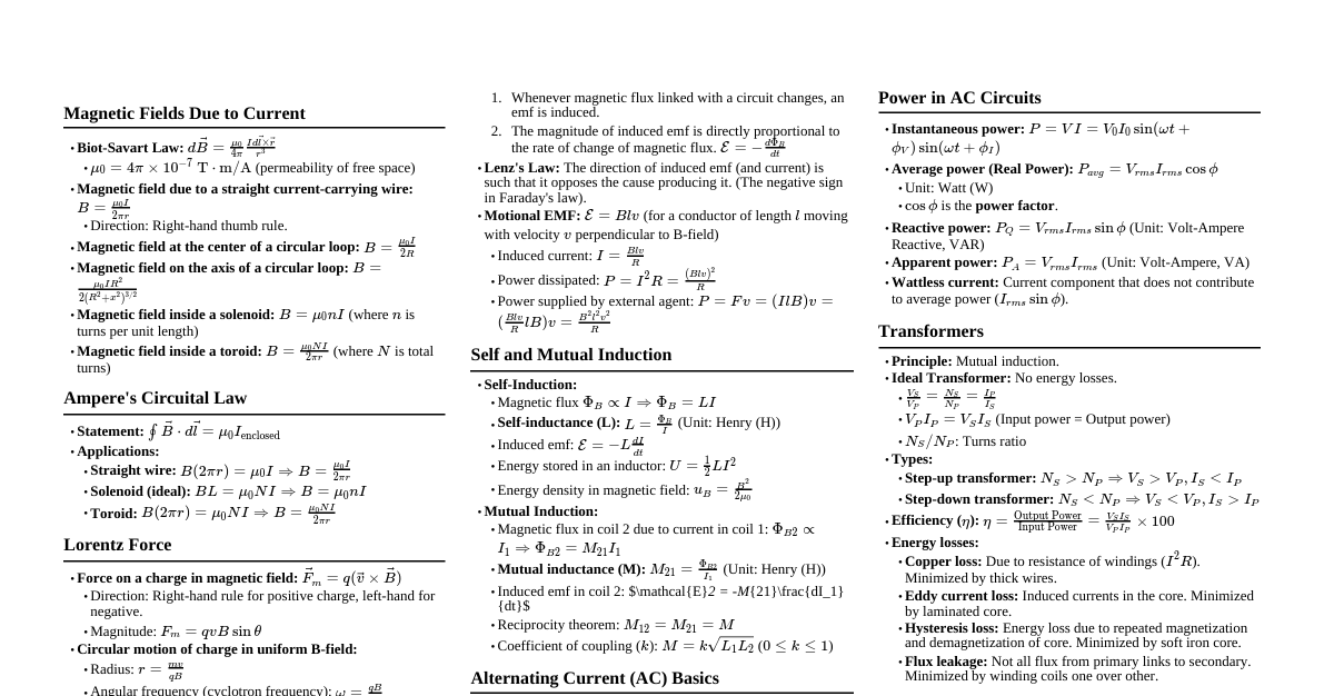
### AC Fundamentals - **Alternating Voltage/Current:** $V = V_0 \sin(\omega t + \phi_V)$, $I = I_0 \sin(\omega t + \phi_I)$ - **Peak Value:** $V_0, I_0$ - **RMS Value:** $V_{rms} = V_0/\sqrt{2} \approx 0.707 V_0$, $I_{rms} = I_0/\sqrt{2} \approx 0.707 I_0$. **(Most common for power calculations)** - **Average Value (Half Cycle):** $V_{avg} = 2V_0/\pi \approx 0.637 V_0$, $I_{avg} = 2I_0/\pi \approx 0.637 I_0$. **(Full cycle average = 0)** - **Angular Frequency:** $\omega = 2\pi f = 2\pi/T$ - **Phase Difference:** $\phi = \phi_V - \phi_I$. If $\phi > 0$, voltage leads current. If $\phi ### Phasor Diagrams & Concept - **Representation:** Rotating vectors (phasors) representing peak values $V_0, I_0$ or RMS values $V_{rms}, I_{rms}$. - **Angle:** Angle with horizontal axis represents phase. Relative angle represents phase difference. - **Use:** Visually determine resultant voltage/current and phase relationships in series/parallel circuits. **(Critical for LCR circuits)** ### AC Circuits: Individual Components #### Resistor (R) - **Voltage:** $V_R = I_R R$ - **Phase:** Voltage and current are in phase ($\phi_R = 0$). - **Phasor:** $V_R$ and $I_R$ are along the same direction. #### Inductor (L) - **Inductive Reactance:** $X_L = \omega L = 2\pi f L$. Unit: Ohm ($\Omega$). - **Voltage:** $V_L = I_L X_L$ - **Phase:** Voltage leads current by $\pi/2$ (90°). **(ELI the ICE man: E leads I in L)** - **Phasor:** $V_L$ is 90° ahead of $I_L$. #### Capacitor (C) - **Capacitive Reactance:** $X_C = 1/(\omega C) = 1/(2\pi f C)$. Unit: Ohm ($\Omega$). - **Voltage:** $V_C = I_C X_C$ - **Phase:** Current leads voltage by $\pi/2$ (90°). **(ICE man: I leads E in C)** - **Phasor:** $V_C$ is 90° behind $I_C$. ### Series LCR Circuit - **Impedance (Z):** $Z = \sqrt{R^2 + (X_L - X_C)^2}$. Unit: Ohm ($\Omega$). **(Total opposition to current flow)** - **Current:** $I = V/Z$ (RMS or Peak values). - **Phase Angle ($\phi$):** $\tan \phi = (X_L - X_C)/R$. If $X_L > X_C$, circuit is inductive, $V$ leads $I$. If $X_C > X_L$, circuit is capacitive, $I$ leads $V$. If $X_L = X_C$, circuit is resistive, $V$ and $I$ are in phase. - **Voltage across components:** $V_R = IR$, $V_L = IX_L$, $V_C = IX_C$. - **Applied Voltage:** $V = \sqrt{V_R^2 + (V_L - V_C)^2}$. **(Vector sum, not algebraic sum)** - **Phasor Diagram:** $V_R$ horizontal, $V_L$ upwards, $V_C$ downwards. Resultant $V$ at angle $\phi$. ### Resonance in Series LCR Circuit - **Condition:** $X_L = X_C \implies \omega_0 L = 1/(\omega_0 C)$ - **Resonant Frequency ($\omega_0$):** $\omega_0 = 1/\sqrt{LC}$ or $f_0 = 1/(2\pi\sqrt{LC})$ - **At Resonance:** - Impedance $Z = R$ (minimum impedance). - Current $I = V/R$ (maximum current). **(Sharpness of resonance)** - Phase angle $\phi = 0$ (circuit is purely resistive). - $V_L = V_C$ (voltages across L and C cancel out). - **Quality Factor (Q-factor):** $Q = (\omega_0 L)/R = 1/(\omega_0 C R) = (1/R)\sqrt{L/C}$. **(Higher Q means sharper resonance, better selectivity)** - **Bandwidth:** $\Delta\omega = \omega_2 - \omega_1 = R/L$. Frequencies where power is half of maximum (half-power frequencies). - **Relationship:** $Q = \omega_0/\Delta\omega$. ### Power in AC Circuits - **Instantaneous Power:** $P_{inst} = V I = V_0 I_0 \sin(\omega t + \phi_V) \sin(\omega t + \phi_I)$ - **Average Power (True Power):** $P_{avg} = V_{rms} I_{rms} \cos\phi$. Unit: Watt (W). - **Power Factor ($\cos\phi$):** $\cos\phi = R/Z$. **(Fraction of apparent power that is real power)** - **Apparent Power:** $S = V_{rms} I_{rms}$. Unit: Volt-Ampere (VA). - **Reactive Power (Wattless Power):** $Q = V_{rms} I_{rms} \sin\phi$. Unit: Volt-Ampere Reactive (VAR). **(Power that oscillates between source and reactive components)** - **Pure Resistive Circuit:** $\phi = 0$, $\cos\phi = 1$, $P_{avg} = V_{rms} I_{rms}$. - **Pure Inductive/Capacitive Circuit:** $\phi = \pm \pi/2$, $\cos\phi = 0$, $P_{avg} = 0$. ### LC Oscillations - **Energy Transfer:** Electrical energy in capacitor $\leftrightarrow$ Magnetic energy in inductor. - **Total Energy:** $U = U_E + U_B = (1/2)CV^2 + (1/2)LI^2 = (1/2)CV_0^2 = (1/2)LI_0^2$. **(Conservation of energy)** - **Angular Frequency of Oscillation:** $\omega_0 = 1/\sqrt{LC}$. - **Equations:** $Q = Q_0 \cos(\omega_0 t + \delta)$, $I = -dQ/dt = I_0 \sin(\omega_0 t + \delta)$. - **Analogy:** LC oscillations are analogous to mass-spring system: - L $\leftrightarrow$ m (Inertia) - C $\leftrightarrow$ 1/k (Compliance) - Q $\leftrightarrow$ x (Displacement) - I $\leftrightarrow$ v (Velocity) ### Transformer - **Principle:** Mutual Induction. - **Turns Ratio:** $N_S/N_P$. - **Voltage Relation:** $V_S/V_P = N_S/N_P = k$ (transformation ratio). - **Current Relation (Ideal Transformer):** $I_S/I_P = N_P/N_S = 1/k$. - **Power (Ideal Transformer):** $P_{in} = P_{out} \implies V_P I_P = V_S I_S$. - **Efficiency ($\eta$):** $\eta = P_{out}/P_{in} = (V_S I_S)/(V_P I_P)$. - **Losses:** Flux leakage, Resistance of windings (Copper loss), Eddy currents, Hysteresis loss. - **Types:** Step-up ($N_S > N_P \implies V_S > V_P, I_S I_P$). ### Choke Coil - **Function:** Controls AC current without significant power loss. - **Construction:** High inductance (L), low resistance (R). - **Power Factor:** $\cos\phi = R/Z = R/\sqrt{R^2 + X_L^2}$. For ideal choke, $R \approx 0$, $\cos\phi \approx 0$, so $P_{avg} \approx 0$. - **Advantage over Resistor:** Resistor dissipates power ($I^2R$), choke coil stores and releases energy, minimal dissipation. ### Question Variations & Common Traps - **RMS vs. Peak vs. Average:** Always check which value is given/asked. Power calculations *always* use RMS. - **Phase Angle Sign:** Carefully determine if voltage leads or lags current. Use ELI ICE man. - **Resonance Conditions:** - **Current:** Max in series LCR. - **Impedance:** Min in series LCR. - **Voltage:** $V_L=V_C$ but $V_L$ or $V_C$ can be greater than applied voltage $V$ (voltage magnification). - **Power Factor:** Often asked directly or implicitly (e.g., "what is the power dissipated?"). Remember $P = V_{rms} I_{rms} \cos\phi$. - **Transformer:** Ideal vs. Real. For real transformers, efficiency is ### Topper-Level Shortcuts & Tricks - **Phasor Algebra (Complex Numbers):** - $Z_R = R$ - $Z_L = jX_L$ - $Z_C = -jX_C = 1/(j\omega C)$ - **Series:** $Z_{total} = R + j(X_L - X_C)$. Magnitude $|Z| = \sqrt{R^2 + (X_L - X_C)^2}$, Phase $\phi = \arctan((X_L - X_C)/R)$. - **Parallel:** $1/Z_{total} = 1/Z_1 + 1/Z_2 + ...$ (Less common for NEET, but useful if encountered). - **Resonance Frequency:** If $L$ is in mH and $C$ in $\mu$F, $f_0 = 1/(2\pi\sqrt{LC})$ will be in kHz for common values. - **Power Factor Calculation:** Always remember $\cos\phi = R/Z$. If you find $Z$ and $R$, $\cos\phi$ is direct. - **Voltage Magnification:** In series resonance, $V_L = Q V_{applied}$ and $V_C = Q V_{applied}$. This can be much larger than the applied voltage. - **LC Oscillation Analogy:** Use the simple harmonic motion (SHM) equations for quick recall of current/charge phase relationships and energy conservation. - Current is max when charge is zero, and vice-versa. - **Transformer Ratios:** $V_S/V_P = N_S/N_P$ and $I_S/I_P = N_P/N_S$. Notice the inverse relationship for current. - **Memory Aid for Phase:** **ELI** (Voltage E leads Current I in Inductor L) and **ICE** (Current I leads Voltage E in Capacitor C). ### Visual Summaries & Mnemonics #### 1. LCR Series Circuit Phasor Map ``` ^ V_L (or I*X_L) | | I, V_R (or I*R) | | v V_C (or I*X_C) - If V_L > V_C, resultant V is in upper half (inductive) - If V_C > V_L, resultant V is in lower half (capacitive) - If V_L = V_C, resultant V is along I (resistive, resonance) ``` #### 2. Power Triangle ``` ^ Reactive Power (Q = VI sin phi) | | / | / |/ Apparent Power (S = VI) +----------- > True Power (P = VI cos phi) phi ``` - **Mnemonic:** "P**R**ime **Q**uality **S**ervices" (P = Real, Q = Reactive, S = Apparent) - **Relationship:** $S^2 = P^2 + Q^2$ #### 3. Impedance Triangle (for Series LCR) ``` ^ X_L | | / Z (Impedance) | / |/ phi +----------- > R (Resistance) | v X_C (if X_C > X_L, then net reactance is downwards) ``` - **Net Reactance:** $X_{net} = X_L - X_C$. So the vertical side is $X_L - X_C$. - **Relationship:** $Z^2 = R^2 + (X_L - X_C)^2$ #### 4. Resonant Frequency Mnemonic - "LC Resonance" -> "Light Current". **L**ight **C**urrent is **R**adiant. $f_0 = 1/(2\pi\sqrt{LC})$ #### 5. Choke Coil Concept - **Choke = Choke current, not power.** - High L, Low R $\implies$ High $X_L$, Low power consumption.