Digital Logic Gates & Circuits
Cheatsheet Content
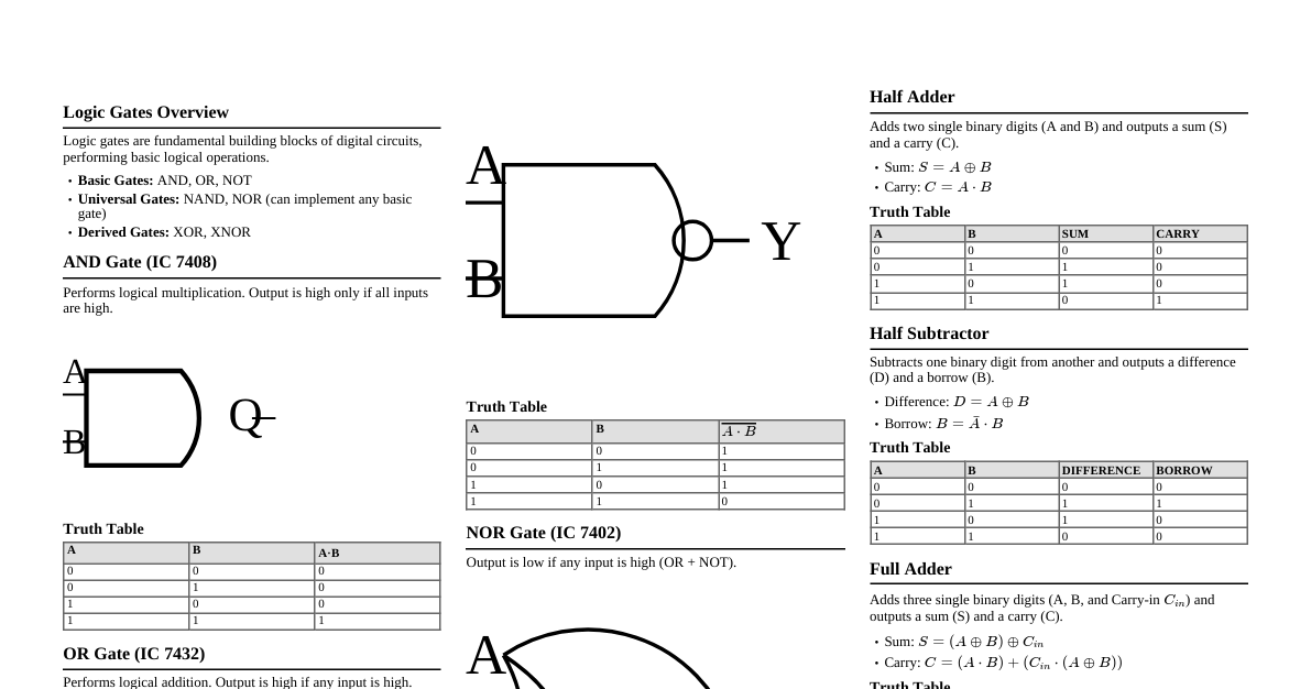
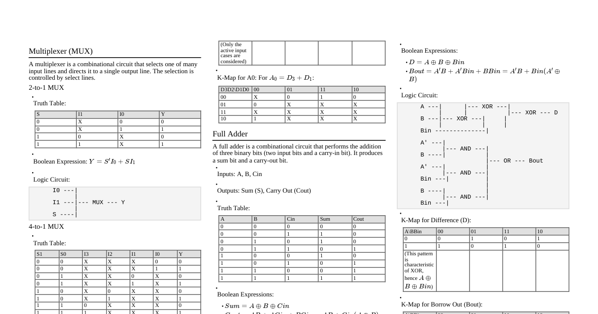
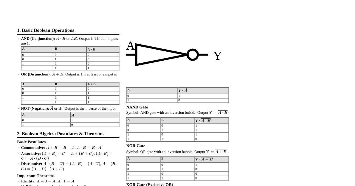
Logic Gates - Basic Operations Logic gates are fundamental building blocks of digital circuits, performing logical operations on one or more binary inputs to produce a single binary output. The primary gates are OR, AND, and NOT. NAND and NOR are universal gates. OR Gate (IC 7432) Function: Logical Addition ($A+B$) Description: Output is HIGH (1) if any input is HIGH (1). Output is LOW (0) only if all inputs are LOW (0). Symbol: A B out Truth Table: A B A+B 0 0 0 0 1 1 1 0 1 1 1 1 AND Gate (IC 7408) Function: Logical Multiplication ($A \cdot B$) Description: Output is HIGH (1) only if all inputs are HIGH (1). Output is LOW (0) if any input is LOW (0). Symbol: A B Q Truth Table: A B A$\cdot$B 0 0 0 0 1 0 1 0 0 1 1 1 NOT Gate (IC 7404) Function: Inversion ($\bar{A}$) Description: Output is the complement of the input. If input is HIGH (1), output is LOW (0), and vice-versa. Symbol: A Q Truth Table: A $\bar{A}$ 0 1 1 0 NAND Gate (IC 7400) Function: NOT-AND ($\overline{A \cdot B}$) Description: Output is LOW (0) only if all inputs are HIGH (1). Output is HIGH (1) if any input is LOW (0). Symbol: A B Y Truth Table: A B $\overline{A \cdot B}$ 0 0 1 0 1 1 1 0 1 1 1 0 NOR Gate (IC 7402) Function: NOT-OR ($\overline{A+B}$) Description: Output is HIGH (1) only if all inputs are LOW (0). Output is LOW (0) if any input is HIGH (1). Symbol: A B Y Truth Table: A B $\overline{A+B}$ 0 0 1 0 1 0 1 0 0 1 1 0 XOR Gate (IC 7486) Function: Exclusive OR ($A \oplus B$) Description: Output is HIGH (1) if inputs are different. Output is LOW (0) if inputs are the same. Symbol: A B Y Truth Table: A B $A \oplus B$ 0 0 0 0 1 1 1 0 1 1 1 0 Boolean Theorems Commutative Law Addition: $A + B = B + A$ (Order of OR-ing variables doesn't matter) Multiplication: $A \cdot B = B \cdot A$ (Order of AND-ing variables doesn't matter) Associative Law Addition: $A + (B + C) = (A + B) + C$ (Grouping of OR-ed variables doesn't matter) Multiplication: $A \cdot (B \cdot C) = (A \cdot B) \cdot C$ (Grouping of AND-ed variables doesn't matter) Truth Table for $A + (B + C) = (A + B) + C$: A B C $B+C$ $A+(B+C)$ $A+B$ $(A+B)+C$ 0 0 0 0 0 0 0 0 0 1 1 1 0 1 0 1 0 1 1 1 1 0 1 1 1 1 1 1 1 0 0 0 1 1 1 1 0 1 1 1 1 1 1 1 0 1 1 1 1 1 1 1 1 1 1 1 Distributive Law $A \cdot (B + C) = (A \cdot B) + (A \cdot C)$ Truth Table for $A \cdot (B + C) = (A \cdot B) + (A \cdot C)$: A B C $B+C$ $A \cdot (B+C)$ $A \cdot B$ $A \cdot C$ $(A \cdot B)+(A \cdot C)$ 0 0 0 0 0 0 0 0 0 0 1 1 0 0 0 0 0 1 0 1 0 0 0 0 0 1 1 1 0 0 0 0 1 0 0 0 0 0 0 0 1 0 1 1 1 0 1 1 1 1 0 1 1 1 0 1 1 1 1 1 1 1 1 1 De Morgan's Theorems Theorem 1: $\overline{A \cdot B} = \bar{A} + \bar{B}$ (Complement of a product is the sum of the complements) Theorem 2: $\overline{A + B} = \bar{A} \cdot \bar{B}$ (Complement of a sum is the product of the complements) Truth Table for $\overline{A \cdot B} = \bar{A} + \bar{B}$: A B $\overline{A \cdot B}$ $\bar{A}$ $\bar{B}$ $\bar{A} + \bar{B}$ 0 0 1 1 1 1 0 1 1 1 0 1 1 0 1 0 1 1 1 1 0 0 0 0 Truth Table for $\overline{A + B} = \bar{A} \cdot \bar{B}$: A B $\overline{A + B}$ $\bar{A}$ $\bar{B}$ $\bar{A} \cdot \bar{B}$ 0 0 1 1 1 1 0 1 0 1 0 0 1 0 0 0 1 0 1 1 0 0 0 0 Combinational Circuits Half Adder Function: Adds two single-bit binary numbers. Inputs: $A, B$ Outputs: Sum ($S$), Carry ($C_{out}$) Equations: $S = A \oplus B$ $C_{out} = A \cdot B$ Truth Table: A B $C_{out}$ $S$ 0 0 0 0 0 1 0 1 1 0 0 1 1 1 1 0 Full Adder Function: Adds three single-bit binary numbers (two inputs and a carry-in). Inputs: $A, B, C_{in}$ Outputs: Sum ($S$), Carry ($C_{out}$) Equations: $S = A \oplus B \oplus C_{in}$ $C_{out} = (A \cdot B) + (B \cdot C_{in}) + (A \cdot C_{in})$ Truth Table: A B $C_{in}$ $C_{out}$ $S$ 0 0 0 0 0 0 0 1 0 1 0 1 0 0 1 0 1 1 1 0 1 0 0 0 1 1 0 1 1 0 1 1 0 1 0 1 1 1 1 1 Half Subtractor Function: Subtracts one single-bit binary number from another. Inputs: $A$ (Minuend), $B$ (Subtrahend) Outputs: Difference ($D$), Borrow ($B_{out}$) Equations: $D = A \oplus B$ $B_{out} = \bar{A} \cdot B$ Truth Table: A B $B_{out}$ $D$ 0 0 0 0 0 1 1 1 1 0 0 1 1 1 0 0 Full Subtractor Function: Subtracts three single-bit binary numbers (two inputs and a borrow-in). Inputs: $A, B, B_{in}$ Outputs: Difference ($D$), Borrow ($B_{out}$) Equations: $D = A \oplus B \oplus B_{in}$ $B_{out} = (\bar{A} \cdot B) + (\bar{A} \cdot B_{in}) + (B \cdot B_{in})$ Truth Table: A B $B_{in}$ $B_{out}$ $D$ 0 0 0 0 0 0 0 1 1 1 0 1 0 1 1 0 1 1 1 0 1 0 0 0 1 1 0 1 0 0 1 1 0 0 0 1 1 1 1 1 4-bit Binary Adder/Subtractor (IC 7483) Function: Performs addition or subtraction of two 4-bit binary numbers based on a mode select input. Mode Select (M): If $M=0$: Performs Addition ($X+Y$) If $M=1$: Performs Subtraction ($X + (1's \text{ complement of } Y) + 1$) (2's complement subtraction) Truth Table (Example): Mode Select Input Data A Input Data B Output Data S.NO MODE (M=0/1) Operation A4 A3 A2 A1 B4 B3 B2 B1 C S4 S3 S2 S1 1 0 Addition 1 0 0 0 0 0 1 0 0 1 0 1 0 1 Subtraction 1 0 0 0 0 0 1 0 0 0 1 1 0 2 0 Addition 1 1 0 1 0 0 1 0 0 1 1 1 1 1 Subtraction 1 1 0 1 0 0 1 0 0 1 0 1 1 Multiplexers (MUX) Function: Selects one of $2^n$ input data lines and routes it to a single output line, based on $n$ select lines. 4:1 Multiplexer: Inputs: $D_0, D_1, D_2, D_3$ (Data Inputs), $S_1, S_0$ (Select Lines) Output: $Y$ Equation: $Y = \overline{S_1}\overline{S_0}D_0 + \overline{S_1}S_0D_1 + S_1\overline{S_0}D_2 + S_1S_0D_3$ Function Table (4:1 MUX): Select Line Values Output $S_1$ $S_0$ $Y$ 0 0 $D_0$ 0 1 $D_1$ 1 0 $D_2$ 1 1 $D_3$ Encoders Function: Converts $2^n$ input lines into an $n$-bit binary output. Only one input can be active at a time. Octal to Binary Encoder (8:3 Encoder): Inputs: $Y_0, Y_1, \dots, Y_7$ (8 input lines) Outputs: $A_2, A_1, A_0$ (3-bit binary output) Truth Table (Octal to Binary Encoder): Inputs Outputs $Y_0$ $Y_1$ $Y_2$ $Y_3$ $Y_4$ $Y_5$ $Y_6$ $Y_7$ $A_2$ $A_1$ $A_0$ 1 0 0 0 0 0 0 0 0 0 0 0 1 0 0 0 0 0 0 0 0 1 0 0 1 0 0 0 0 0 0 1 0 0 0 0 1 0 0 0 0 0 1 1 0 0 0 0 1 0 0 0 1 0 0 0 0 0 0 0 1 0 0 1 0 1 0 0 0 0 0 0 1 0 1 1 0 0 0 0 0 0 0 0 1 1 1 1 Decoders Function: Converts an $n$-bit binary input into $2^n$ output lines, where only one output is active based on the input code. 2 to 4 Decoder: Inputs: $A, B$ (2-bit binary input), $E$ (Enable) Outputs: $Y_0, Y_1, Y_2, Y_3$ (4 output lines) Truth Table (2 to 4 Decoder): Inputs Outputs Enable (E) A B $Y_0$ $Y_1$ $Y_2$ $Y_3$ 0 X X 0 0 0 0 1 0 0 1 0 0 0 1 0 1 0 1 0 0 1 1 0 0 0 1 0 1 1 1 0 0 0 1 BCD Adder Function: Adds two BCD (Binary Coded Decimal) digits in parallel, producing a BCD sum and a carry. Steps for BCD Addition: Add the two BCD numbers using binary addition. If the 4-bit sum is $\le 9$, it is a valid BCD number. If the 4-bit sum is $> 9$ or if a carry out of the 4-bit group is generated, it is an invalid result. Add $6 (0110_2)$ to the 4-bit sum to correct it. If a carry results when $6$ is added, add this carry to the next 4-bit group. Truth Table for BCD Adder: SL.NO $A_4$ $A_3$ $A_2$ $A_1$ $B_4$ $B_3$ $B_2$ $B_1$ C $S_4$ $S_3$ $S_2$ $S_1$ 1 0 0 0 1 0 0 1 0 0 0 1 1 1 2 0 1 1 0 1 0 0 0 1 0 1 0 0 3 1 0 0 1 1 0 1 0 1 1 0 0 1 Magnitude Comparators Function: Compares two binary numbers ($A$ and $B$) and determines if $A > B$, $A 2-bit Magnitude Comparator: Inputs: $A_1A_0$, $B_1B_0$ Outputs: $G (A>B)$, $E (A=B)$, $L (A Equations (from K-map): $E = (\overline{A_0 \oplus B_0}) \cdot (\overline{A_1 \oplus B_1})$ $L = \bar{A_1}B_1 + \bar{A_0}\bar{A_1}B_0 + \bar{A_0}B_1B_0$ $G = A_1\bar{B_1} + A_0A_1\bar{B_0} + A_0\bar{B_0}\bar{B_1}$ Truth Table: Inputs A Inputs B Outputs $A_1$ $A_0$ $B_1$ $B_0$ $A>B$ $A=B$ $A 0 0 0 0 0 1 0 0 0 0 1 0 0 1 0 0 1 0 0 0 1 0 0 1 1 0 0 1 0 1 0 0 1 0 0 0 1 0 1 0 1 0 0 1 1 0 0 0 1 0 1 1 1 0 0 1 1 0 0 0 1 0 0 1 0 0 1 1 0 0 1 0 1 0 0 1 0 1 0 1 1 0 0 1 1 1 0 0 1 0 0 1 1 0 1 1 0 0 1 1 1 0 1 0 0 1 1 1 1 0 1 0 4-bit Magnitude Comparator (IC 7485): Can be cascaded for comparing larger numbers. Counters 3-bit Synchronous Up Counter Function: Counts from 000 to 111 (or specified sequence) in response to clock pulses. All flip-flops are clocked simultaneously. State Diagram: Counts $000 \to 001 \to 010 \to 011 \to 100 \to 101 \to 110 \to 111 \to 000 \dots$ JK Flip-Flop Excitation Table: Q $Q_{t+1}$ J K 0 0 0 X 0 1 1 X 1 0 X 1 1 1 X 0 Truth Table (Up Counter): Clock Pulse (CP) Q1 Q2 Q3 0 0 0 0 1 0 0 1 2 0 1 0 3 0 1 1 4 1 0 0 5 1 0 1 6 1 1 0 7 1 1 1 8 0 0 0 3-bit Synchronous Down Counter Function: Counts from 111 to 000 (or specified sequence) in response to clock pulses. State Diagram: Counts $000 \to 111 \to 110 \to 101 \to 100 \to 011 \to 010 \to 001 \to 000 \dots$ Truth Table (Down Counter): Clock Pulse (CP) Q1 Q2 Q3 0 0 0 0 1 1 1 1 2 1 1 0 3 1 0 1 4 1 0 0 5 0 1 1 6 0 1 0 7 0 0 1 8 0 0 0 3-bit Synchronous Up/Down Counter Function: Counts up or down based on a control input (e.g., UP/DOWN signal). Universal Shift Registers (D Flip-Flops) Function: A register capable of storing data and shifting data left or right, with parallel loading capability. Can operate in serial and parallel modes. D Flip-Flop (IC 7474) Pin Diagram (Example): clr1 D1 clk1 Pr1 Q1 $\overline{Q1}$ GND Vcc Clr2 D2 Clk2 Pr2 Q2 $\overline{Q2}$ D F/F Pos. Edge triggered Clock 7474 Control Modes: $S_1$ $S_0$ Register Operation 0 0 No change 0 1 Shift right 1 0 Shift left 1 1 Parallel load Logisim Simulator Overview Purpose: Open-source tool for designing and simulating digital logic circuits. Key Features: Graphical interface for circuit design using gates, plexers, arithmetic units, memory, I/O. Simultaneous editing and simulation. Hierarchical design: reuse smaller circuits (e.g., 1-bit adder) to build larger ones (e.g., 4-bit adder). Wiring elements: pins, splitters (for converting buses to individual wires and vice versa). Color-coded signals in simulation mode for easy debugging: Gray: Unknown bit width. Blue: Known value, unknown bit width. Dark Green: Value 0. Light Green: Value 1. Black: Multiple bits (bus). Red: Error or undefined value. Orange: Incorrect bit width connection.