BEEE Essentials
Cheatsheet Content
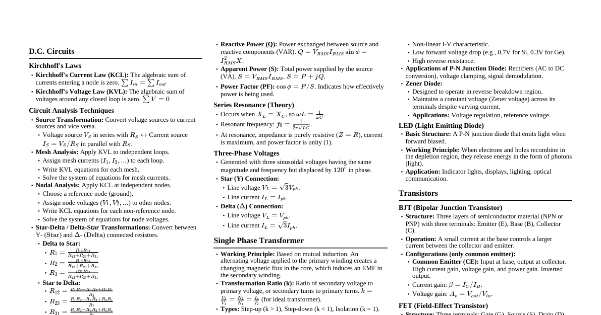
Circuit Analysis Techniques Source Transformation: Simplifies complex resistive networks by converting voltage sources to current sources and vice-versa. Voltage source $V_S$ in series with resistor $R$: Equivalent to current source $I_S = V_S/R$ in parallel with $R$. Current source $I_S$ in parallel with resistor $R$: Equivalent to voltage source $V_S = I_S \cdot R$ in series with $R$. Superposition Theorem: Used to find current or voltage in a linear circuit with multiple independent sources. Calculate contribution from each independent source individually (turning off others: voltage sources shorted, current sources opened). Total response is the algebraic sum of individual responses. Not applicable for power calculations directly because power is a non-linear function ($P=I^2R$ or $P=V^2/R$). Thevenin's Theorem: Any linear two-terminal circuit can be replaced by an equivalent circuit consisting of a voltage source $V_{Th}$ in series with a resistor $R_{Th}$. $V_{Th}$: Open-circuit voltage across the terminals. $R_{Th}$: Equivalent resistance looking into the terminals with all independent sources turned off. Conditions: Linearity, two-terminal network. Norton's Theorem: Any linear two-terminal circuit can be replaced by an equivalent circuit consisting of a current source $I_N$ in parallel with a resistor $R_N$. $I_N$: Short-circuit current across the terminals. $R_N$: Equivalent resistance looking into the terminals with all independent sources turned off ($R_N = R_{Th}$). Conditions: Linearity, two-terminal network. Nodal Analysis: Applies KCL at each non-reference node. Steps: Assign node voltages, write KCL equations, solve system of equations. Mesh Analysis: Applies KVL around each independent loop (mesh). Steps: Assign mesh currents, write KVL equations, solve system of equations. Semiconductor Physics Drift Current: Movement of charge carriers (electrons and holes) due to an electric field. $J_{drift} = (nq\mu_n + pq\mu_p)E$ $n, p$: electron/hole concentration; $q$: elementary charge; $\mu_n, \mu_p$: electron/hole mobility; $E$: electric field. Diffusion Current: Movement of charge carriers due to a concentration gradient (from high to low concentration). $J_{diff} = qD_n \frac{dn}{dx} - qD_p \frac{dp}{dx}$ $D_n, D_p$: electron/hole diffusion coefficients. Direct vs. Indirect Band Gap Semiconductors: Direct Band Gap: Minimum of conduction band and maximum of valence band occur at the same momentum ($k$) value. Electrons can directly recombine with holes, emitting photons. Efficient light emitters (e.g., GaAs, GaN). Indirect Band Gap: Minimum of conduction band and maximum of valence band occur at different $k$ values. Recombination requires a phonon (lattice vibration) to conserve momentum. Less efficient light emitters (e.g., Si, Ge). PN Junction Diode: Formed by joining p-type and n-type semiconductors. Forward Bias: Positive voltage applied to p-side, negative to n-side. Reduces depletion region width, allows current flow. Reverse Bias: Negative voltage applied to p-side, positive to n-side. Increases depletion region width, blocks current (except for small reverse saturation current). Reverse Saturation Current ($I_0$): Small current due to minority carrier diffusion across the junction in reverse bias. Increases with temperature. Dynamic Resistance: Resistance to small signal changes. Forward bias: Low dynamic resistance. Reverse bias: High dynamic resistance. Zener Diode: Heavily doped PN junction designed to operate in reverse breakdown. Zener Breakdown: Occurs due to high electric field causing electrons to tunnel from valence to conduction band. Avalanche Breakdown: Occurs due to high electric field accelerating carriers, which then collide with lattice atoms, generating more carriers. Voltage Regulation: Maintains a constant output voltage across its terminals when operating in the reverse breakdown region. Energy Band Model: Explains conductivity differences. Conductors: Overlapping valence and conduction bands, or very small band gap. Many free electrons. Semiconductors: Small band gap. Conductivity increases with temperature (electrons jump to conduction band). Insulators: Large band gap. Very few electrons can reach conduction band, very low conductivity. Digital Electronics Gray Code: A non-weighted code where successive values differ by only one bit. Minimizes errors: In digital encoders, a single bit change reduces the chance of misreading during transitions. Functionally Complete Gates: A set of logic gates from which all other Boolean functions can be constructed. NAND and NOR gates are functionally complete: Any logic gate (AND, OR, NOT) can be implemented using only NAND or only NOR gates. Boolean Function Minimization: Karnaugh Maps (K-maps): Graphical method to simplify Boolean expressions by grouping adjacent '1's (or '0's) into largest possible rectangles. Quine-McCluskey Algorithm: Tabular method for minimizing Boolean functions, especially for more variables than K-maps are practical. Combinational Hazards: Undesired momentary output changes in combinational circuits caused by varying propagation delays through different paths. Static Hazards: Output momentarily goes to 0 when it should stay 1 (static-1 hazard) or to 1 when it should stay 0 (static-0 hazard). Dynamic Hazards: Output changes more than once when it should change only once. Mitigation: Add redundant terms to K-map groupings. Race-Around Condition (in Latches/Flip-Flops): In a JK flip-flop, if J=K=1 and the clock pulse is wide, the output can toggle multiple times within a single clock pulse, leading to an unpredictable state. Mitigation: Edge-triggered flip-flops, master-slave flip-flops. Propagation Delay: Time taken for a signal to propagate from input to output of a logic gate or circuit. Effect on Synchronous Sequential Circuits: Too long a propagation delay can cause setup time or hold time violations, leading to incorrect state transitions. Determines the maximum operating frequency. Shift Registers: Serial-In Serial-Out (SISO): Data enters and exits one bit at a time. Slower for data transfer. Parallel-In Parallel-Out (PIPO): Data enters and exits all bits simultaneously. Faster for data transfer. Data Integrity: Both maintain data integrity if operated correctly. Timing is critical for synchronous operation. Flip-Flop Conversions: JK to T Flip-Flop: Connect J and K inputs together. The common input becomes the T input. ($T = J = K$). $Q_{next} = T \oplus Q$. Master-Slave JK Flip-Flop: Consists of two cascaded JK flip-flops (master and slave). Master is enabled on the rising edge (or high level) of the clock, slave on the falling edge (or low level). Eliminates race-around condition by ensuring the output changes only once per clock cycle. Rectifiers Half-Wave Rectifier: Allows only one half-cycle of the AC input voltage to pass through to the load. Output is pulsating DC. Circuit: Single diode in series with AC source and load. Parameters: Average DC Current ($I_{dc}$): $I_m/\pi$ Average DC Voltage ($V_{dc}$): $V_m/\pi$ RMS Current ($I_{rms}$): $I_m/2$ DC Power Output ($P_{dc}$): $I_{dc}^2 R_L$ or $V_{dc}^2 / R_L$ AC Power Input ($P_{ac}$): $I_{rms}^2 (R_f + R_L)$ Efficiency ($\eta$): $P_{dc}/P_{ac} \approx 40.6\%$ (ideal) Ripple Factor ($\gamma$): $\sqrt{(\frac{I_{rms}}{I_{dc}})^2 - 1} \approx 1.21$ Full-Wave Rectifier (Bridge Rectifier): Converts both positive and negative half-cycles of AC input into pulsating DC output. Circuit: Four diodes arranged in a bridge configuration. Parameters (compared to HWR): Higher $V_{dc}$, $I_{dc}$, efficiency ($\approx 81.2\%$), lower ripple factor ($\approx 0.48$). With Capacitor Filter: Capacitor charges during peak voltage, discharges through load during valleys, smoothing the output DC. Reduces ripple. Transformer Utilization Factor (TUF): Ratio of DC power delivered to the load to the AC power rating of the transformer secondary. Indicates how effectively the transformer is used. Diode Characteristics & Applications Diode Equation (Shockley Diode Equation): $I = I_0 (e^{V/(\eta V_T)} - 1)$ $I$: Diode current; $I_0$: Reverse saturation current; $V$: Voltage across diode; $\eta$: Ideality factor (1 for Ge, 1-2 for Si); $V_T$: Thermal voltage ($kT/q$). Tunnel Diode: Heavily doped PN junction exhibiting negative differential resistance. Construction: Very narrow depletion region due to heavy doping. Working Principle: Quantum mechanical tunneling of electrons. V-I Characteristics: Peak current, valley current, and a region where current decreases as voltage increases (negative resistance). Applications: High-speed switching, oscillators. Digital System Design Gray Code to Binary Converter: Convert Gray code $G_n G_{n-1} \dots G_1 G_0$ to Binary $B_n B_{n-1} \dots B_1 B_0$. $B_n = G_n$ $B_{i-1} = G_{i-1} \oplus B_i$ (for $i=n$ down to $1$) 4-bit Parallel Adder-Subtractor: Uses full adders. A control signal ($M$) determines addition ($M=0$) or subtraction ($M=1$). For subtraction ($A-B$): $A + (\text{2's complement of } B) = A + \bar{B} + 1$. $M$ controls XOR gates at each B input (to get $\bar{B}$) and is also connected to the carry-in of the first full adder (to add 1). Flip-Flop Excitation Tables: $Q_n$ $Q_{n+1}$ JK SR D T 0 0 0X 0X 0 0 0 1 1X 10 1 1 1 0 X1 01 0 1 1 1 X0 X0 1 0 Shift Register Design: Typically uses D flip-flops for simple implementation, as their output directly follows the input after a clock pulse, making data shifting straightforward.