Industrial Drives Essentials
Cheatsheet Content
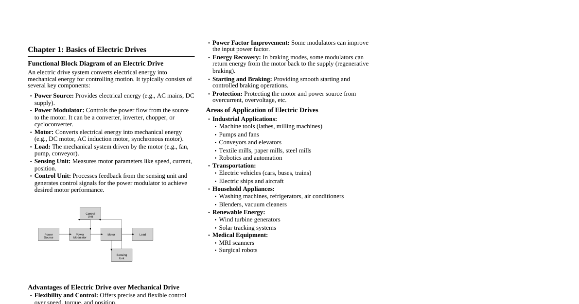
Chapter 1: Basics of Electric Drives Draw and explain functional block diagram of an Electric Drive. An electric drive system converts electrical energy into mechanical energy for controlling motion. Functional Block Diagram: Power Source Power Modulator Motor Load Controller Sensing Unit Components: Power Source: Provides electrical energy (AC or DC). Power Modulator: Converts electrical energy into a form suitable for the motor (e.g., rectifier, inverter, chopper). Controls voltage, current, and frequency. Electric Motor: Converts electrical energy into mechanical energy. Common types: DC motors, Induction motors, Synchronous motors. Load: The mechanical system to be driven (e.g., pump, fan, conveyor). Controller: Regulates the power modulator based on command signals and feedback, ensuring desired motor performance. Sensing Unit: Measures motor parameters like speed, current, and position, providing feedback to the controller. Why electric drive is preferred over mechanical drive? (Advantages) Flexibility: Easy speed control over a wide range. Efficiency: Higher overall efficiency, especially at varying loads. Control: Precise and smooth control of speed, torque, and position. Automation: Easily integrated into automated systems. Maintenance: Generally lower maintenance compared to complex mechanical systems. Environment: Cleaner operation, no exhaust fumes. Starting Characteristics: Smooth starting and braking without mechanical shocks. Space: Often more compact for a given power output. Compare between AC drives and DC drives. Feature AC Drives DC Drives Motor Type AC motors (Induction, Synchronous) DC motors (Shunt, Series, Compound, PM) Complexity More complex control circuitry (inverters) Simpler control circuitry (choppers, rectifiers) Maintenance Low maintenance (brushless motors) High maintenance (brushes, commutator) Efficiency Generally high Good, but can be lower due to brush losses Speed Control Excellent, wide range (V/f control) Good, but limited at very low speeds Cost Higher initial cost for variable frequency drives Lower initial cost for basic drives Applications Fans, pumps, compressors, industrial machinery Elevators, cranes, traction, automotive Briefly explain the need for an electric drive system. Precise Control: Many industrial processes require accurate control of speed, torque, and position. Energy Efficiency: Optimized operation to save energy, especially with varying load conditions. Automation & Integration: Essential for modern automated manufacturing and process control. Versatility: Adaptable to various load characteristics and operational requirements. Reduced Wear & Tear: Smooth acceleration and deceleration minimize mechanical stress on machinery. Safety: Provides better control over machinery, enhancing operational safety. What is an Electric Drive / Electric Drive System? An electric drive is an electromechanical system used to control the motion of an electric motor and its associated mechanical load. It consists of a power source, a power modulator, an electric motor, a mechanical transmission system, and a control unit. Its primary function is to convert electrical energy into mechanical energy in a controlled manner, providing precise speed, torque, and position control for various industrial and domestic applications. What are the functions of a power modulator? Energy Conversion: Converts electrical energy from the source into a form suitable for the motor (e.g., AC to DC, DC to AC, DC to variable DC, AC to variable AC). Voltage Control: Regulates the voltage supplied to the motor to control its speed and torque. Current Control: Limits or controls the current flowing through the motor for protection and performance. Frequency Control: For AC motors, it controls the frequency of the supply to achieve variable speed operation. Power Flow Control: Manages the direction of power flow (motoring or regenerative braking). Protection: Provides protection against overcurrent, overvoltage, undervoltage, etc. Examples include rectifiers, inverters, choppers, and AC voltage controllers. Point out some areas of application of Electric drive. Industrial: Conveyors, pumps, fans, compressors, machine tools, rolling mills, textile mills, paper mills. Transportation: Electric vehicles, electric trains, trams, elevators, escalators. Domestic: Washing machines, refrigerators, air conditioners, vacuum cleaners, mixers. Robotics: Robotic arms, automated guided vehicles (AGVs). Renewable Energy: Wind turbines (generator control), solar tracking systems. Medical: MRI machines, surgical robots. Chapter 2: DC Motor Drives (Converter & Control) 1-phase full-wave fully controlled converter drive for separately excited DC motor (Circuit & Waveforms). A 1-phase full-wave fully controlled converter (dual converter) uses SCRs to rectify AC to variable DC voltage for a separately excited DC motor armature. Circuit Diagram: (Imagine a bridge rectifier with 4 SCRs, with the DC output connected to the armature of a separately excited DC motor, and the field winding connected to a separate DC supply). $V_s \sin(\omega t)$ T1 T2 T3 T4 M Armature F Field DC Source Operation: During the positive half-cycle of AC input, SCRs T1 and T4 are forward biased. They are triggered at a firing angle $\alpha$. During the negative half-cycle, SCRs T2 and T3 are forward biased and triggered at $\pi + \alpha$. The output voltage $V_o$ is a pulsating DC voltage, whose average value can be controlled by varying $\alpha$. Average output voltage: $V_{dc} = \frac{2V_m}{\pi} \cos(\alpha)$, where $V_m$ is the peak AC input voltage. Since $V_{dc} \propto E_b + I_a R_a$, controlling $V_{dc}$ directly controls the motor speed. Waveforms: (Idealized for continuous current) Input Voltage ($V_s$): Sinusoidal AC. Output Voltage ($V_o$ across motor armature): Rectified sinusoidal segments starting from $\alpha$ and $\pi+\alpha$. Armature Current ($I_a$): If inductance is high, current can be continuous and relatively smooth, following the average voltage. It is assumed to be continuous for this explanation. $\omega t$ $V_s$ $-V_s$ Input Voltage ($V_s$) Output Voltage ($V_o$) $\alpha$ $\pi+\alpha$ $2\pi+\alpha$ Explain different braking methods in DC motor with diagram. Braking is used to stop or slow down the motor and its load. 1. Regenerative Braking: Principle: The motor acts as a generator, converting mechanical energy from the load into electrical energy, which is fed back to the power source. Condition: Occurs when the back EMF ($E_b$) becomes greater than the supply voltage ($V$), and the armature current reverses direction. This happens when the motor speed is higher than the no-load speed for the given supply voltage. Advantage: Energy saving. Diagram (DC Shunt Motor): $V$ M Back EMF $E_b$ Current Direction 2. Dynamic (Rheostatic) Braking: Principle: The motor is disconnected from the supply, and its armature is connected across a braking resistor. The kinetic energy of the rotating parts is dissipated as heat in the resistor. Advantage: Simple and effective for quick stopping. Diagram (DC Shunt Motor): M $R_b$ Back EMF $E_b$ 3. Plugging (Reversed Voltage Braking): Principle: The armature terminals are reversed while the motor is still running. This causes the supply voltage and back EMF to act in the same direction, producing a large braking current and torque. Advantage: Very quick and effective braking. Disadvantage: High power loss and potential for damage due to high current; requires current limiting. Diagram (DC Shunt Motor): $V$ M Back EMF $E_b$ Current Direction Polarity Reversed Explain different speed control methods of DC motor. The speed of a DC motor is given by $N \propto \frac{V - I_a R_a}{\phi}$, where $N$ is speed, $V$ is supply voltage, $I_a$ is armature current, $R_a$ is armature resistance, and $\phi$ is field flux. 1. Armature Voltage Control (for speeds below rated): Principle: By varying the armature voltage ($V$) while keeping the field flux constant, the speed can be controlled. Lowering $V$ reduces speed. Method: Usually achieved using choppers or controlled rectifiers. Characteristics: Provides constant torque operation (torque is proportional to $I_a \phi$, and $\phi$ is constant). Speed range from zero to rated speed. Applications: Machine tools, centrifuges, elevators. 2. Field Flux Control (for speeds above rated): Principle: By varying the field current ($I_f$), the field flux ($\phi$) can be controlled. Reducing $I_f$ (and thus $\phi$) increases the motor speed. Method: A rheostat in series with the field winding or a controlled converter for the field supply. Characteristics: Provides constant power operation (power $P = T \omega$, and $T \propto \phi I_a$. If $\phi$ decreases, $I_a$ must increase to maintain constant power). Speed range from rated speed upwards. Applications: Lathes, boring mills, printing presses. 3. Armature Resistance Control (Rheostatic Control): Principle: Inserting an external resistance ($R_{ext}$) in series with the armature circuit. This increases $R_a$, thus reducing the speed for a given voltage. Method: A variable rheostat connected in series with the armature. Characteristics: Speed is reduced below rated speed. Inefficient due to power loss ($I_a^2 R_{ext}$) in the resistor. Provides a stepless speed control but with poor speed regulation. Applications: Cranes, hoists (for starting and short-duration speed control). Torque-speed characteristics of separately excited DC motor. For a separately excited DC motor: Back EMF: $E_b = K_e \phi \omega$ Torque: $T = K_t \phi I_a$ Armature circuit equation: $V = E_b + I_a R_a$ Substituting $I_a = \frac{V - E_b}{R_a}$ into the torque equation: $T = K_t \phi \frac{V - K_e \phi \omega}{R_a}$ $T = \frac{K_t \phi V}{R_a} - \frac{K_t K_e \phi^2 \omega}{R_a}$ This equation shows a linear relationship between torque ($T$) and speed ($\omega$) for a constant supply voltage $V$ and constant field flux $\phi$. Characteristics: No-load speed ($\omega_0$): When $T=0$, $\omega_0 = \frac{V}{K_e \phi}$. Starting torque ($T_{st}$): When $\omega=0$, $T_{st} = \frac{K_t \phi V}{R_a}$. Slope: The slope of the $T-\omega$ curve is negative, given by $-\frac{K_t K_e \phi^2}{R_a}$. Constant Flux (Rated Speed Operation): The $T-\omega$ curve is a straight line with a negative slope. Speed decreases slightly with increasing load. Armature Voltage Control (below rated speed): By reducing $V$, the no-load speed shifts down, resulting in a family of parallel $T-\omega$ curves. This provides constant torque operation. Field Weakening Control (above rated speed): By reducing $\phi$, the no-load speed increases, and the slope of the $T-\omega$ curve becomes less steep. This provides constant power operation. Diagram: Speed ($\omega$) Torque ($T$) $V_1, \phi_1$ $V_2 $V_1, \phi_2 Torque-Speed Characteristics Briefly explain the chopper DC drive for a DC series motor. A chopper is a static DC-DC converter that converts fixed DC input voltage to a variable DC output voltage. For a DC series motor drive, a chopper is used to vary the average voltage applied to the motor armature and field winding (which are in series). Principle: The chopper rapidly switches the DC supply ON and OFF. By varying the duty cycle ($\alpha = T_{on}/T$), the average output voltage ($V_o = \alpha V_{in}$) can be controlled. Circuit: A basic step-down (buck) chopper consists of a power semiconductor switch (e.g., MOSFET, IGBT), a freewheeling diode, and an inductor. The series motor armature and field are connected across the output of the chopper. $V_{in}$ SW FD F A Series Motor Speed Control: By varying the duty cycle $\alpha$ of the chopper, the average voltage across the series motor is controlled. Increasing $\alpha$ increases the average voltage, leading to higher speed. Decreasing $\alpha$ reduces the average voltage, leading to lower speed. Advantages: High efficiency, smooth speed control, regenerative braking possible with multi-quadrant choppers. Applications: Electric traction (locomotives, trams), forklifts, battery-operated vehicles. Explain operation of a 3-phase fully controlled converter for DC drive. A 3-phase fully controlled converter (six-pulse converter) uses six SCRs to rectify a 3-phase AC supply into a variable DC voltage, commonly used for high-power DC motor drives. Circuit: Consists of six SCRs arranged in a bridge configuration, connected to a 3-phase AC source on one side and the DC motor armature on the other. R Y B T1 T3 T5 T4 T6 T2 M Armature Operation: The six SCRs are divided into two groups: three positive group SCRs (T1, T3, T5) connected to the positive DC rail, and three negative group SCRs (T2, T4, T6) connected to the negative DC rail. SCRs are fired in sequence with a phase difference of $60^\circ$. For example, T1, T2, T3, T4, T5, T6, T1... Conduction occurs in pairs: one SCR from the positive group and one from the negative group conduct simultaneously (e.g., T1 and T2). The output DC voltage is controlled by varying the firing angle ($\alpha$) of the SCRs. Average output voltage: $V_{dc} = \frac{3V_{mL}}{\pi} \cos(\alpha)$, where $V_{mL}$ is the peak line-to-line input voltage. By varying $\alpha$ from $0^\circ$ to $180^\circ$, the output voltage can be varied from maximum positive to maximum negative, allowing for both motoring and regenerative braking. Advantages: Provides smooth and wide range control of DC motor speed and torque, inherent regenerative braking capability, high power handling. Applications: High-power industrial DC drives like steel rolling mills, paper mills, traction systems, and cement kilns. Numerical: 1400 RPM, 20A separately excited DC motor with bridge rectifier. This is a general problem statement. A complete numerical problem would require specific values for voltage, resistance, and operating conditions. Typical calculations involve: Motor Constants: Calculate $K_e \phi$ and $K_T \phi$ from given data (e.g., no-load speed, rated torque). Back EMF: $E_b = V_{dc} - I_a R_a$. Speed: $N \propto E_b$. $N = K \cdot E_b / \phi$. Torque: $T = K_T \phi I_a$. Rectifier Output Voltage: For a single-phase full-wave bridge rectifier, average output voltage $V_{dc} = \frac{2V_m}{\pi} \cos(\alpha)$. For a 3-phase, $V_{dc} = \frac{3V_{mL}}{\pi} \cos(\alpha)$. Example (Illustrative, not a full solution): A separately excited DC motor is supplied by a single-phase full-wave controlled bridge rectifier. The motor ratings are 200V, 20A, 1400 RPM. Armature resistance $R_a = 1 \Omega$. AC source voltage is 230V, 50Hz. Field current is constant. Rated back EMF: $E_b = V - I_a R_a = 200 - (20 \times 1) = 180V$. At 1400 RPM, $E_b = 180V$. So, $K \phi = 180/1400$. If the rectifier's firing angle is $\alpha$, the average voltage supplied to the motor is $V_{dc} = \frac{2 \times (230\sqrt{2})}{\pi} \cos(\alpha)$. Then, $E_b' = V_{dc} - I_a' R_a$. New speed $N' = \frac{E_b'}{K \phi} = \frac{E_b'}{180/1400}$. If current is 20A at some speed, we would calculate $E_b$ and then $N$. Numerical: 800 RPM, 80A separately excited DC motor speed calculation. Similar to the above, this is a general context. To calculate speed, we need: Armature voltage ($V_{dc}$) supplied by the converter. Armature current ($I_a$). Armature resistance ($R_a$). Motor constant ($K_e \phi$) or a reference speed/voltage relationship. Steps: Calculate the back EMF ($E_b$) at the given operating point: $E_b = V_{dc} - I_a R_a$. If a reference speed ($N_{ref}$) and corresponding back EMF ($E_{b,ref}$) are known (e.g., from rated conditions or another operating point), use the proportionality: $\frac{N}{N_{ref}} = \frac{E_b}{E_{b,ref}}$. Solve for the new speed $N = N_{ref} \times \frac{E_b}{E_{b,ref}}$. Example (Illustrative): A separately excited DC motor operates at 1000 RPM with 200V armature voltage and 50A armature current. $R_a = 0.5 \Omega$. Calculate the speed if the armature voltage is reduced to 180V and armature current is 80A. Reference condition: $E_{b,ref} = V_{ref} - I_{a,ref} R_a = 200 - (50 \times 0.5) = 200 - 25 = 175V$. New condition: $E_b = V - I_a R_a = 180 - (80 \times 0.5) = 180 - 40 = 140V$. New speed: $N = 1000 \times \frac{140}{175} = 1000 \times 0.8 = 800 \text{ RPM}$. Numerical: Regenerative braking calculation for DC motor. Regenerative braking occurs when $E_b > V$. The motor acts as a generator, and current direction reverses. Key Equations: Armature circuit: $V = E_b + I_a R_a$ (motoring) or $V = E_b - I_a R_a$ (generating, $I_a$ is braking current). Braking Current: $I_a = \frac{E_b - V}{R_a}$. This current flows out of the armature. Braking Torque: $T_b = K_T \phi I_a$. Power fed back: $P_{regen} = V \cdot I_a$. Example (Illustrative): A DC shunt motor has $R_a = 0.2 \Omega$, rated voltage $V = 220V$. At a certain speed, its back EMF is $230V$. Calculate the braking current and braking torque if $K_T \phi = 1.5 \text{ Nm/A}$. Since $E_b (230V) > V (220V)$, regenerative braking occurs. Braking current: $I_a = \frac{E_b - V}{R_a} = \frac{230 - 220}{0.2} = \frac{10}{0.2} = 50 \text{ A}$. Braking torque: $T_b = K_T \phi I_a = 1.5 \times 50 = 75 \text{ Nm}$. Numerical: 240V shunt motor speed reduction using series resistance ($R_x$). Principle: Adding an external resistance $R_x$ in series with the armature reduces the effective voltage across the armature, thus reducing speed. Key Equation: Original: $V = E_b + I_a R_a$ With $R_x$: $V = E_b' + I_a' (R_a + R_x)$ Speed $N \propto E_b$. Example (Illustrative): A 240V DC shunt motor has $R_a = 0.4 \Omega$. When driving a load, it draws 50A and runs at 1200 RPM. Calculate the value of series resistance required to reduce the speed to 900 RPM, assuming the load torque (and thus armature current) remains constant. Original Back EMF: $E_b = V - I_a R_a = 240 - (50 \times 0.4) = 240 - 20 = 220V$. At 1200 RPM, $E_b = 220V$. New speed $N' = 900 \text{ RPM}$. Since $N \propto E_b$, the new back EMF $E_b'$ is: $E_b' = E_b \times \frac{N'}{N} = 220 \times \frac{900}{1200} = 220 \times 0.75 = 165V$. With constant load torque, $I_a'$ also remains 50A. New armature circuit equation: $V = E_b' + I_a' (R_a + R_x)$. $240 = 165 + 50 (0.4 + R_x)$. $240 - 165 = 50 (0.4 + R_x)$. $75 = 20 + 50 R_x$. $55 = 50 R_x$. $R_x = \frac{55}{50} = 1.1 \Omega$. Numerical: 200V DC series motor speed calculation (Load torque +44%). Principle: For a DC series motor, flux $\phi \propto I_a$. So, $E_b = K I_a \omega$ and $T = K I_a^2$. Key Equations: $V = E_b + I_a (R_a + R_{se})$ $E_b = K_e \phi \omega = K_e' I_a \omega$ $T = K_t \phi I_a = K_t' I_a^2$ Example (Illustrative): A 200V DC series motor takes 20A and runs at 1000 RPM. Total resistance $(R_a+R_{se}) = 0.5 \Omega$. If the load torque increases by 44%, calculate the new speed and current. Initial Back EMF: $E_b_1 = V - I_{a1} (R_a+R_{se}) = 200 - (20 \times 0.5) = 200 - 10 = 190V$. Initial Torque: $T_1 = K I_{a1}^2 = K (20)^2 = 400K$. New Torque: $T_2 = T_1 \times 1.44 = 400K \times 1.44 = 576K$. New Current: Since $T \propto I_a^2$, $I_{a2}^2 = \frac{T_2}{K} = \frac{576K}{K} = 576$. So, $I_{a2} = \sqrt{576} = 24 \text{ A}$. New Back EMF: $E_{b2} = V - I_{a2} (R_a+R_{se}) = 200 - (24 \times 0.5) = 200 - 12 = 188V$. Speed relationship: $\frac{N_2}{N_1} = \frac{E_{b2}}{E_{b1}} \times \frac{I_{a1}}{I_{a2}}$ (since $\phi \propto I_a$, so $N \propto E_b/\phi \propto E_b/I_a$). $N_2 = N_1 \times \frac{E_{b2}}{E_{b1}} \times \frac{I_{a1}}{I_{a2}} = 1000 \times \frac{188}{190} \times \frac{20}{24} = 1000 \times 0.989 \times 0.833 \approx 824 \text{ RPM}$. Chapter 3: AC Motor Drives (Induction Motor Control) 3-phase induction motor speed control by V/f (Voltage/Frequency) control. Principle: The synchronous speed of an induction motor is $N_s = \frac{120f}{P}$, where $f$ is frequency and $P$ is number of poles. The induced EMF in the stator is $E \propto \phi f$. To maintain constant air-gap flux ($\phi$) and thus constant torque, the ratio of voltage to frequency ($V/f$) must be kept constant. Operation: A variable frequency drive (VFD) or inverter is used to change both the supply voltage ($V$) and frequency ($f$) simultaneously, maintaining a constant $V/f$ ratio. Below Base Speed: As frequency is reduced, voltage is proportionally reduced to keep $V/f$ constant. This allows for constant torque operation. Above Base Speed (Field Weakening): Once the rated voltage is reached, further increase in speed requires increasing frequency beyond the base frequency without increasing voltage. This results in a decreasing $V/f$ ratio, which means the flux decreases. This mode provides constant power operation but with reduced torque capability. Advantages: Wide range of smooth speed control (from zero to well above rated speed). High efficiency and good power factor. Constant torque operation below base speed. Constant power operation above base speed. Improved starting and braking characteristics. Diagram (Torque-Speed Characteristics): Speed Torque $f_1$ $f_2 $f_3 V/f Control Characteristics Applications: Most industrial applications requiring variable speed, such as pumps, fans, conveyors, machine tools, and rolling mills. Compare Current Source Inverters (CSI) and Voltage Source Inverters (VSI). Feature Current Source Inverter (CSI) Voltage Source Inverter (VSI) DC Link Inductor in DC link (current source) Capacitor in DC link (voltage source) Output Constant current, variable voltage Constant voltage, variable current Commutation Load or forced commutation (SCRs) Self-commutation (IGBTs, MOSFETs) Motor Type Suitable for synchronous motors, large induction motors Suitable for all AC motors, especially induction motors Protection Inherently short-circuit protected Requires fast overcurrent protection Regeneration Easy, inherent bidirectional power flow Requires additional circuitry for regeneration Output Waveform Stepped current waveform Stepped voltage waveform (PWM for sinusoidal) Harmonics Current harmonics are high Voltage harmonics are high (reduced by PWM) Cost Generally higher for similar performance Generally lower, especially for PWM inverters Explain starting methods of an induction motor. Induction motors draw very high starting current (5-7 times full load current) and produce low starting torque if started direct-on-line (DOL). Starting methods aim to reduce starting current and/or improve starting torque. 1. Direct-On-Line (DOL) Starter: Principle: The motor is directly connected to the full supply voltage. Advantages: Simple, cheapest. Disadvantages: High starting current, high starting torque (can damage mechanical load), voltage dips in the supply. Application: Small motors (up to 5 HP). 2. Stator Rheostat (Primary Resistor) Starting: Principle: Resistors are connected in series with the stator winding during starting to reduce the voltage across the motor. Once the motor speeds up, the resistors are bypassed. Advantages: Reduced starting current, smooth acceleration. Disadvantages: Significant power loss in resistors, reduced starting torque. Application: Medium-sized motors where smooth acceleration is required. 3. Autotransformer (Auto-starter) Starting: Principle: An autotransformer is used to apply a reduced voltage to the stator during starting. After the motor accelerates, the autotransformer is disconnected, and the motor is connected to full supply voltage. Advantages: Reduced starting current, higher starting torque compared to stator rheostat. Disadvantages: More complex and expensive than DOL. Application: Medium to large motors. 4. Star-Delta (Y-Δ) Starting: Principle: The stator windings are initially connected in Star (Y) for starting, which applies $\frac{1}{\sqrt{3}}$ times the phase voltage, effectively reducing the voltage. Once the motor reaches a certain speed, the windings are reconnected in Delta (Δ) for normal operation. Advantages: Reduced starting current (1/3 of DOL current), reduced starting torque (1/3 of DOL torque). Disadvantages: Only applicable to motors designed for delta connection during normal run, requires 6 terminals. Application: Medium-sized motors (generally 5 HP to 100 HP). 5. Soft Starter: Principle: Uses solid-state devices (SCRs or triacs) to gradually increase the voltage to the motor, providing a smooth start. Advantages: Very smooth acceleration, reduced mechanical stress, energy saving. Disadvantages: More expensive than traditional starters. Application: Where very smooth start/stop and reduced mechanical shock are critical (e.g., pumps, conveyors). 6. Variable Frequency Drive (VFD) Starting: Principle: The VFD applies reduced voltage and frequency at startup and gradually increases both, maintaining a constant V/f ratio. Advantages: Optimal starting torque, minimum starting current, highly efficient, precise control. Disadvantages: Most expensive. Application: All applications where precise speed control and high efficiency are required. Working of capacitor start and capacitor run induction motor. These are types of single-phase induction motors. Single-phase induction motors are not self-starting; they require an auxiliary winding to create a rotating magnetic field. 1. Capacitor-Start Induction Motor: Principle: It has a main winding and an auxiliary (starting) winding. A capacitor is connected in series with the auxiliary winding and a centrifugal switch. The capacitor creates a phase shift between the currents in the main and auxiliary windings, producing a rotating magnetic field to start the motor. Operation: At startup, both windings are energized. The capacitor causes the current in the auxiliary winding to lead the current in the main winding by approximately $90^\circ$ (or close to it), creating a strong starting torque. Once the motor reaches about 70-80% of its synchronous speed, the centrifugal switch opens, disconnecting the auxiliary winding and the capacitor. The motor then runs solely on the main winding as a single-phase induction motor. Characteristics: High starting torque, moderate efficiency. Applications: Pumps, compressors, washing machines, refrigerators. 2. Capacitor-Run Induction Motor (Permanent-Split Capacitor Motor): Principle: Similar to capacitor-start, but the auxiliary winding and capacitor remain in the circuit during both starting and running. The capacitor is typically of a smaller value than a starting capacitor. Operation: The capacitor provides a phase shift for starting and also helps to improve the power factor and efficiency during running. Since the auxiliary winding and capacitor are permanently connected, there is no centrifugal switch. Characteristics: Lower starting torque compared to capacitor-start motors, but better running performance (higher efficiency, better power factor, quieter operation). Applications: Fans, blowers, air conditioners, oil burners, where moderate starting torque and continuous operation are needed. 3. Capacitor-Start Capacitor-Run Motor: Combines features of both. It uses two capacitors: a larger starting capacitor (disconnected by a centrifugal switch) for high starting torque, and a smaller running capacitor (permanently connected) for improved running performance. Applications: Heavy-duty applications requiring high starting torque and continuous efficient operation. Static rotor resistance control of an induction motor. This method is applicable only to slip-ring (wound rotor) induction motors. Principle: By inserting external resistance in the rotor circuit, the rotor impedance is increased. This affects the torque-speed characteristics of the motor. Operation: External resistances are connected in series with the rotor windings via slip rings and brushes. According to the torque equation for an induction motor, $T \propto \frac{s E_2^2 R_2}{R_2^2 + (s X_2)^2}$, where $s$ is slip, $E_2$ is rotor induced EMF, $R_2$ is rotor resistance, and $X_2$ is rotor reactance. Adding external resistance ($R_{ext}$) increases $R_2$ to $(R_2 + R_{ext})$. This shifts the maximum torque point ($s_{max} = R_2/X_2$) to a higher slip (lower speed). By varying the external resistance, the speed at which the motor operates for a given load torque can be controlled. Higher resistance leads to lower speed for the same torque. Advantages: Provides high starting torque with low starting current. Smooth speed control below synchronous speed. Simple control circuit. Disadvantages: Significant power loss ($I_2^2 R_{ext}$) in the external resistors, leading to poor efficiency, especially at low speeds. Speed regulation is poor. Only applicable to slip-ring motors. Applications: Cranes, hoists, elevators, and other applications requiring high starting torque and limited speed control range where efficiency is not critical. Effect of increasing supply frequency over base frequency on torque and slip. When supply frequency ($f$) is increased beyond the base frequency (rated frequency) while keeping the voltage ($V$) constant, the $V/f$ ratio decreases. Effect on Flux ($\phi$): Since $E \propto \phi f$, if $V$ is constant (and thus $E$ is approximately constant), and $f$ increases, the flux $\phi$ must decrease. This is known as "field weakening." Effect on Torque ($T$): Torque is proportional to $\phi I_2 \cos \theta_2$. Since flux $\phi$ decreases, the maximum torque (breakdown torque) of the motor decreases significantly. The operating torque capability of the motor is reduced. This region is known as the "constant power region," as the power output remains relatively constant while torque drops and speed increases. Effect on Slip ($s$): The synchronous speed $N_s = \frac{120f}{P}$ increases with increasing frequency. The slip at maximum torque, $s_{max} = R_2/X_2$, where $X_2 = 2\pi f L_2$. As $f$ increases, $X_2$ increases, so $s_{max}$ decreases. This means the maximum torque occurs at a lower slip (closer to synchronous speed) in percentage terms. Summary: Flux: Decreases ($\phi \propto V/f$). Maximum Torque: Decreases (proportional to $\phi^2$). Operating Torque: Decreases. Synchronous Speed: Increases. Slip at Max Torque: Decreases. This mode is used to achieve speeds above the base speed, but at the expense of reduced torque. Variable voltage square wave six-step inverter using DC link. This is a basic type of Voltage Source Inverter (VSI) used to convert DC to variable frequency AC for motor control. "Six-step" refers to the output voltage waveform, which approximates a sinusoid by six distinct steps over a cycle. DC Link: The DC link is a DC voltage bus, typically obtained by rectifying an AC supply. A large capacitor is used across the DC link to smooth the voltage, making it a "voltage source." Circuit: Consists of six power semiconductor switches (e.g., IGBTs, MOSFETs) arranged in three legs, each connected to one phase of the AC motor. Freewheeling diodes are connected in anti-parallel with each switch. $V_{dc}$ GND Cap S1 S4 A S3 S6 B S5 S2 C Motor Operation (Six-Step Mode, $180^\circ$ conduction): Each switch conducts for $180^\circ$ of the output cycle. At any instant, three switches are ON (one from each leg's upper half, or two from upper and one from lower, etc.). For example, S1, S6, S5 conduct for $60^\circ$, then S1, S2, S5, and so on. The output voltage is a sequence of rectangular pulses, which combine to form a quasi-square wave line-to-line voltage waveform with six distinct steps per half cycle. The frequency is controlled by the switching rate of the devices. The output voltage magnitude can be varied by controlling the DC link voltage (e.g., using a controlled rectifier before the inverter), thus achieving variable V/f control. Disadvantages: High harmonic content in the output voltage, leading to motor losses and acoustic noise. Modern drives largely use PWM (Pulse Width Modulation) techniques to generate smoother, near-sinusoidal outputs. Applications: Older or simpler variable speed AC drives. State advantages of squirrel cage induction motors over DC motors. 1. Robustness and Simplicity: Squirrel cage motors have a very simple and rugged rotor construction (no windings, no slip rings, no brushes). This makes them highly durable and requires very little maintenance. 2. Lower Maintenance: Absence of brushes and commutators eliminates brush wear, sparking, and commutator cleaning/replacement, which are common issues with DC motors. This leads to reduced downtime and lower maintenance costs. 3. Cost-Effective: Generally cheaper to manufacture for the same power rating due to simpler design. 4. Reliability: Fewer parts mean fewer points of failure, leading to higher reliability. 5. Operation in Hazardous Environments: No sparks from brushes make them suitable for explosive or flammable atmospheres without special enclosures. 6. Efficiency: Modern squirrel cage induction motors, especially when controlled by VFDs, can achieve very high efficiencies. 7. Size and Weight: For the same power output, they can be more compact and lighter than DC motors. 8. Power Source: Directly operate from standard AC mains supply, which is readily available. DC motors require an AC-DC converter. Numerical: Starting current and torque calculation (75% voltage / Star-Delta). This refers to starting an induction motor with reduced voltage. Key Relationships: Starting Current $I_{st} \propto V$ (supply voltage). Starting Torque $T_{st} \propto V^2$. Example (Illustrative - 75% Voltage): A 3-phase induction motor has a DOL starting current of 5 times full-load current ($I_{FL}$) and a DOL starting torque of 1.5 times full-load torque ($T_{FL}$). If the motor is started with 75% of its rated voltage, calculate the new starting current and torque. Reduced Voltage $V' = 0.75 V_{rated}$. New Starting Current $I_{st}' = I_{st,DOL} \times \frac{V'}{V_{rated}} = (5 I_{FL}) \times 0.75 = 3.75 I_{FL}$. New Starting Torque $T_{st}' = T_{st,DOL} \times \left(\frac{V'}{V_{rated}}\right)^2 = (1.5 T_{FL}) \times (0.75)^2 = 1.5 T_{FL} \times 0.5625 = 0.84375 T_{FL}$. Example (Illustrative - Star-Delta Starting): Using the same motor as above, calculate starting current and torque if started with a Star-Delta starter. In Star connection, the phase voltage is $V_p/\sqrt{3}$ compared to Delta connection. So, the effective voltage applied to each phase winding is $1/\sqrt{3}$ times the line voltage. Line current in Star is $1/3$ of the line current in Delta (for the same applied line voltage). New Starting Current $I_{st,Y} = I_{st,DOL} \times \frac{1}{3} = (5 I_{FL}) \times \frac{1}{3} = 1.67 I_{FL}$. New Starting Torque $T_{st,Y} = T_{st,DOL} \times \frac{1}{3} = (1.5 T_{FL}) \times \frac{1}{3} = 0.5 T_{FL}$. Chapter 4: Slip Power Recovery Schemes Compare between static Kramer's drive and static Scherbius drive. Feature Static Kramer's Drive Static Scherbius Drive Slip Power Recovery Slip power fed back to AC supply via rectifier and inverter. Slip power fed back to AC supply via rectifier and inverter. Rotor Circuit Rotor connected to diode bridge rectifier, then DC link, then line-commutated inverter. Rotor connected to diode bridge rectifier, then DC link, then forced-commutated inverter (or cycloconverter for subsynchronous/supersynchronous). Speed Range Subsynchronous speeds only (motor mode). Subsynchronous and supersynchronous speeds (for static Scherbius using cycloconverter or forced-commutated inverter). Power Factor Poor power factor, especially at low speeds, due to line-commutated inverter. Better power factor, especially if forced-commutated inverter or PWM rectifier is used. Harmonics High harmonics injected into AC supply due to line-commutated inverter. Reduced harmonics with forced-commutated inverter/PWM rectifier. Control Complexity Simpler control for subsynchronous operation. More complex control, especially for supersynchronous. Applications Large fans, pumps, compressors, where only subsynchronous speed control is needed. Higher performance applications, requiring wider speed range or better power quality. DC Link Current source DC link (inductor). Voltage source DC link (capacitor). Explain power recovery scheme using static converter (Block Diagram). Slip power recovery schemes are used with slip-ring induction motors to recover the energy normally dissipated as heat in the rotor resistance, thus improving efficiency. Block Diagram (General Static Scherbius Drive): AC Supply IM Stator Rotor (Slip Rings) Rectifier DC Link Inverter Transformer Working Principle: The slip power, which is $s P_g$ (where $s$ is slip and $P_g$ is air-gap power), is extracted from the rotor circuit of a slip-ring induction motor. This AC slip power, whose frequency is $s f$ (slip frequency), is first rectified into DC using a diode bridge rectifier. The DC power then flows through a DC link (either inductive for current-source or capacitive for voltage-source). An inverter converts this DC power back into AC power at line frequency. A transformer then steps up the voltage and feeds this recovered AC power back into the main AC supply. By controlling the firing angle of the inverter (in Kramer drives) or the voltage/current of the inverter (in Scherbius drives), the amount of power fed back can be controlled, thereby controlling the motor speed. Advantages: High efficiency due to slip power recovery. Wide range of speed control (subsynchronous and potentially supersynchronous). Reduced motor losses and improved power factor compared to rotor resistance control. Applications: Large pumps, fans, compressors, mine hoists, cement kilns, rolling mills where energy efficiency and speed control are critical for high-power slip-ring induction motors. To which kind of motor slip-power recovery is used and its advantage? Kind of Motor: Slip-power recovery schemes are exclusively used for slip-ring (wound rotor) induction motors . They cannot be applied to squirrel-cage induction motors because the rotor circuit of a squirrel-cage motor is not accessible externally. Advantages of Slip-Power Recovery: Energy Saving/Increased Efficiency: The primary advantage is the recovery of slip power, which would otherwise be dissipated as heat in the rotor resistance. This significantly improves the overall efficiency of the drive, especially at lower speeds where slip is high. Wide Range Speed Control: It provides a wide and smooth range of speed control, typically below synchronous speed (subsynchronous) and, with advanced schemes, also above synchronous speed (supersynchronous). Improved Power Factor: Depending on the type of converter used (e.g., forced-commutated inverter or active rectifier), slip power recovery schemes can also improve the overall power factor of the drive system. Reduced Heat Dissipation: Less heat is generated in the rotor, leading to cooler operation and potentially longer motor life. Reduced Operating Costs: Due to higher efficiency, the operating costs are lower compared to traditional rotor resistance control. Chapter 5: Special Motor Drives & Sensors Construction and principle of operation of Brushless DC (BLDC) motor. Construction: Stator: Typically made of laminated steel, similar to an induction motor. It carries 3-phase (or more) windings, which are positioned to produce a rotating magnetic field when energized. Rotor: Consists of permanent magnets (usually rare-earth magnets like Neodymium) mounted on the rotor surface or embedded within the rotor core. There are no windings, brushes, or commutator on the rotor. Hall Effect Sensors (or other position sensors): These are typically mounted on the stator and detect the rotor's position. This feedback is crucial for sequencing the stator winding energization. (Sensorless control is also possible using back EMF). Electronic Controller: A power electronic converter (inverter) drives the stator windings, and a controller (microcontroller/DSP) processes the position sensor feedback to determine which windings to energize and when. Principle of Operation: BLDC motors operate on the principle of electronic commutation. Instead of mechanical brushes and a commutator, an electronic controller switches the current to the stator windings. The controller uses feedback from the Hall sensors (or sensorless method) to determine the exact position of the rotor's permanent magnets. Based on the rotor position, the controller energizes the appropriate stator windings in a specific sequence (e.g., two phases ON at a time for a 3-phase motor) to create a magnetic field that is always $90^\circ$ electrically ahead of the rotor's magnetic field. This continuous interaction between the stator's electromagnetic field and the rotor's permanent magnet field produces a continuous torque, causing the rotor to rotate. By varying the frequency and magnitude of the applied voltage/current to the stator windings, the speed and torque of the motor can be precisely controlled. Diagram (Conceptual): Stator Windings (Phase A) Phase B Phase C N S H1 H2 H3 BLDC Motor Concept Advantages: High efficiency, high power density, compact size, quiet operation, long life, precise control, no maintenance. Applications: Electric vehicles, drones, robotics, medical equipment, computer peripherals (hard drives, fans). Differences between AC servo motor and DC servo motor. Feature AC Servo Motor DC Servo Motor Motor Type Synchronous (permanent magnet) or Induction motor Permanent magnet DC motor (brushed or brushless) Rotor Permanent magnets (PMSM) or squirrel cage (induction type) Armature winding with commutator and brushes (brushed) or permanent magnets (brushless DC) Stator Poly-phase windings Field winding (wound field) or permanent magnets (PMDC) Commutation Electronic commutation (inverter) Mechanical (brushes & commutator) or electronic (BLDC) Maintenance Low (brushless design) High (brushed) or Low (brushless DC) Inertia Typically low inertia (for dynamic response) Can be low or high inertia Power Rating Available in a wide range, often preferred for higher power More common in lower to medium power applications Control Complex control (vector control / FOC) with VFD Simpler control (voltage/current control) with chopper/rectifier Performance Excellent dynamic response, high accuracy, high torque at high speeds Good dynamic response, high torque at low speeds (brushed), but limitations due to brushes Cost Higher (motor + complex drive) Lower for brushed, comparable for BLDC Classify stepper motors and state their main uses. Stepper motors are DC motors that divide a full rotation into a number of equal steps. They are primarily used for precise position control without feedback (open-loop control). Classification: 1. Permanent Magnet (PM) Stepper Motor: Construction: Rotor consists of permanent magnets. Stator has salient poles with windings. Operation: When stator windings are energized, the rotor's permanent magnets align with the magnetic field created by the energized stator poles. Reversing the current in a winding reverses pole polarity, causing the rotor to step. Characteristics: Provides relatively high torque, larger step angles (e.g., $45^\circ$, $90^\circ$). Uses: Simpler applications where high precision is not paramount, e.g., automotive applications, simple printers. 2. Variable Reluctance (VR) Stepper Motor: Construction: Rotor is made of soft iron (no permanent magnets) with salient poles. Stator also has salient poles with windings. Operation: The rotor moves to a position where the reluctance of the magnetic path is minimized when a specific stator winding is energized. Characteristics: Simple construction, low rotor inertia, high speeds possible, no detent torque (holding torque when unenergized). Smaller step angles (e.g., $15^\circ$). Uses: Older designs, less common now due to hybrid types. 3. Hybrid Stepper Motor: Construction: Combines features of both PM and VR types. Rotor has permanent magnets with toothed structures, and the stator also has toothed poles. Operation: Utilizes both permanent magnet and variable reluctance principles for its torque production. Characteristics: High resolution (small step angles, e.g., $1.8^\circ$, $0.9^\circ$), high torque, good dynamic performance, high detent torque. Most popular type. Uses: Widely used in precision positioning applications: 3D printers, CNC machines, robotics, scanners, plotters, disk drives. Main Uses of Stepper Motors (General): Positioning Systems: Robotics, CNC machines, 3D printers, plotters, medical equipment, camera platforms. Fluid Control: Valve control, fluid pumps. Office Automation: Printers, scanners, copiers, fax machines. Automotive: Fuel injection systems, idle control, cruise control. Consumer Electronics: Disk drives, optical drives. DC servomotors (Short Note). A DC servomotor is a DC motor specifically designed for use in a feedback control system (servo system) where precise control of position, speed, or torque is required. Key Characteristics: High Torque-to-Inertia Ratio: Designed for rapid acceleration and deceleration. Linear Torque-Current Relationship: Torque is directly proportional to armature current, allowing for precise torque control. Linear Speed-Voltage Relationship: Speed is directly proportional to applied voltage over a wide range. Smooth Operation: Capable of very smooth rotation, even at low speeds. Fast Response: Quick response to control signals due to low electrical and mechanical time constants. Types: Brushed DC Servomotor: Traditional DC motor with brushes and commutator. Simpler to control but requires maintenance. Brushless DC (BLDC) Servomotor: Essentially a permanent magnet synchronous motor with electronic commutation. Offers high efficiency, low maintenance, and excellent performance. (Often referred to as AC servomotors due to their drive using an inverter, but their internal operation is similar to a DC motor with electronic commutation). Control System: A DC servomotor is always part of a closed-loop system. It typically includes: Motor: The prime mover. Sensor: An encoder or resolver for position/speed feedback. Controller: A PID controller or similar algorithm to compare desired and actual values. Driver: A power electronic amplifier (e.g., DC chopper or H-bridge) to supply power to the motor based on controller output. Applications: Robotics, CNC machines, industrial automation, medical equipment, aerospace, printing, packaging. Short note on Hall sensors. Hall Effect: The Hall effect states that when a current-carrying conductor or semiconductor is placed in a magnetic field perpendicular to the current flow, a voltage (Hall voltage) is generated across the conductor perpendicular to both the current and the magnetic field. Hall Sensor: A Hall sensor is a transducer that varies its output voltage in response to a magnetic field. Construction: Typically consists of a thin rectangular semiconductor material (e.g., silicon, gallium arsenide) with four terminals: two for current input and two for Hall voltage output. Operation in Motors: In BLDC motors, Hall sensors are strategically placed on the stator (usually three sensors, $120^\circ$ or $60^\circ$ apart electrically). As the permanent magnets on the rotor rotate, they pass by the Hall sensors, creating varying magnetic fields. Each sensor generates a logic HIGH or LOW signal depending on the polarity of the magnetic field (North or South) passing it. These digital signals provide precise information about the instantaneous angular position of the rotor. The motor controller uses this position feedback to determine which stator windings to energize next, ensuring proper electronic commutation and continuous rotation. Advantages: Solid-state device, fast response, robust, can operate in harsh environments, contactless sensing. Applications: BLDC motor commutation, speed sensing, position sensing, current sensing, magnetic field detection, automotive (crankshaft/camshaft position). Short note on Speed regulation. Definition: Speed regulation is a measure of how much the speed of a motor changes from no-load to full-load conditions, expressed as a percentage of the full-load speed or no-load speed. Formula: $\text{Speed Regulation (SR)} = \frac{N_{NL} - N_{FL}}{N_{FL}} \times 100\%$ where: $N_{NL}$ is the no-load speed (speed when load torque is zero). $N_{FL}$ is the full-load speed (speed when the motor is driving its rated load). Interpretation: A lower percentage of speed regulation indicates better speed stability (i.e., the speed changes less between no-load and full-load). An ideal motor would have 0% speed regulation, meaning its speed remains constant regardless of the load. However, in practice, all motors have some degree of speed drop with increasing load. Factors Affecting Speed Regulation: DC Motors: Armature resistance ($R_a$), field strength ($\phi$). Higher $R_a$ leads to poorer regulation. Induction Motors: Rotor resistance ($R_2$), stator resistance ($R_1$), leakage reactances. Higher resistances lead to poorer regulation. Improvement: Closed-loop control systems (with speed feedback) are commonly used to achieve very tight speed regulation, essentially making the speed independent of load variations. Using motors with low armature resistance (for DC) or low rotor resistance (for AC). Importance: Good speed regulation is crucial in applications where constant speed is critical, such as precision machining, textile machinery, and constant-speed conveyors. Chapter 6: Starters, Control Hardware & Duty Cycles Sketch control and power circuits of Automatic Star-Delta Starter. A Star-Delta (Y-Δ) starter is a reduced voltage starting method for 3-phase squirrel cage induction motors. Principle: The motor stator windings are initially connected in Star (Y) during starting, and after a timed interval, they are reconnected in Delta (Δ) for normal running. Power Circuit: (Requires 6 motor terminals) 3-Phase Supply KM OL U1 V1 W1 U2 V2 W2 KD KS Power Circuit Control Circuit: (Simplified using push buttons, timer, and contactor coils) L1 L2 OL Stop Start KM KM T KM KS KM T KD KM T Control Circuit Operation: Start (Star Connection): When the "Start" button is pressed, the main contactor (KM) and the Star contactor (KS) are energized. The motor windings are connected in Star, receiving reduced voltage ($V_{phase} = V_{line}/\sqrt{3}$). The timer (T) also starts. Run (Delta Connection): After a preset time (e.g., 5-10 seconds), the timer's normally closed (NC) contact opens, de-energizing the Star contactor (KS). Simultaneously, the timer's normally open (NO) contact closes, energizing the Delta contactor (KD). The motor windings are then reconnected in Delta, receiving full line voltage for normal operation. Interlocking: Electrical interlocking (using NC contacts of KS and KD in the opposite coil circuits) is essential to prevent both Star and Delta contactors from being ON simultaneously, which would cause a short circuit. Reversing direction of induction motor with interlocking systems (Diagram). To reverse the direction of rotation of a 3-phase induction motor, the phase sequence of the supply to the stator windings must be reversed. This is typically done by interchanging any two of the three supply lines. Power Circuit: (Forward and Reverse contactors) 3-Phase Supply KF KR OL M Power Circuit Control Circuit with Interlocking: L1 L2 OL Stop Fwd Rev KF KR KR KF KF KR Control Circuit Interlocking System: Electrical Interlocking: In the control circuit, a normally closed (NC) contact of the "Reverse" contactor (KR) is placed in series with the "Forward" contactor (KF) coil, and an NC contact of KF is placed in series with the KR coil. This ensures that if KF is energized, KR cannot be energized, and vice-versa. This prevents a direct short circuit across the supply lines. Mechanical Interlocking: Some contactors have mechanical interlocks built-in, which physically prevent both contactors from closing simultaneously. This provides an additional layer of safety. Operation: Pressing the "Forward" button energizes KF, causing the motor to rotate in the forward direction. Pressing the "Reverse" button energizes KR, causing the motor to rotate in the reverse direction (after stopping or if a brief delay is implemented). The "Stop" button de-energizes both contactors. Phase-Locked Loop (PLL) speed control of DC motor drive. A Phase-Locked Loop (PLL) is a control system that generates an output signal whose phase is related to the phase of an input (reference) signal. When applied to motor speed control, it provides highly accurate and precise speed regulation. Block Diagram: Reference Frequency ($f_{ref}$) Phase Detector Loop Filter Power Converter DC Motor Speed Sensor Working Principle: Reference Frequency ($f_{ref}$): A stable, high-precision reference frequency (or pulse train) representing the desired motor speed is provided. Speed Sensor: A speed sensor (e.g., an optical encoder or tachogenerator) measures the actual motor speed and converts it into a feedback frequency ($f_{fb}$). Phase Detector (PD): The phase detector compares the phase (and implicitly, frequency) of the reference signal ($f_{ref}$) with the feedback signal ($f_{fb}$). It generates an error voltage proportional to the phase difference between the two signals. Loop Filter: This filter (typically a low-pass filter) smooths the error voltage from the phase detector, removing high-frequency noise and providing a stable DC control voltage. It also determines the dynamic response and stability of the PLL. Power Converter: The filtered error voltage is fed to the power converter (e.g., a controlled rectifier or chopper for a DC motor). The converter adjusts the armature voltage supplied to the DC motor. DC Motor: The motor speed changes in response to the adjusted armature voltage. Feedback: The change in motor speed affects the feedback frequency, completing the loop. The PLL continuously adjusts the motor speed until the feedback frequency matches the reference frequency, meaning the phase difference is zero. Advantages: Extremely high accuracy and precision in speed control, excellent speed regulation, robust against load disturbances, stable operation. Applications: High-precision applications such as robotics, CNC machine tools, industrial automation, scientific instruments, and any system requiring very tight speed synchronization. Explain intermittent duty cycle. Duty Cycle: Describes the pattern of loading on a motor over time. It specifies periods of operation and rest. Intermittent Duty Cycle: In this type of duty cycle, a motor operates for a short period, followed by a period of rest, and this cycle repeats. The idle period is long enough for the motor to cool down to ambient temperature, or close to it, before the next operating period begins. Characteristics: Operating Period (ON time): The motor runs and heats up. Rest Period (OFF time): The motor is de-energized and cools down. This period is significant. Thermal Equilibrium: The key feature is that the motor does not reach its maximum permissible temperature during the operating period, and it cools down sufficiently during the rest period. Therefore, the RMS value of the current (and thus heating) is lower than if it were continuously running. Types of Intermittent Duty: (According to IEC 60034-1) S2 - Short-Time Duty: Operation at constant load for a given time, insufficient to reach thermal equilibrium, followed by a rest period long enough for the motor to cool down. (e.g., S2-10min) S3 - Intermittent Periodic Duty: A sequence of identical run and rest periods. Starting current has no significant effect on temperature rise. (e.g., S3-25% ED - 25% Electrical Duty/Duty Cycle) S4 - Intermittent Periodic Duty with Starting: Similar to S3, but starting current significantly affects temperature rise. S5 - Intermittent Periodic Duty with Electric Braking: Similar to S4, but electric braking also significantly affects temperature rise. Implications: Motors designed for intermittent duty cycles can have smaller frame sizes or higher power ratings for a given frame size compared to continuously rated motors, as they are not subjected to continuous thermal stress. Applications: Cranes, hoists, elevators, machine tools (e.g., drilling, punching), pumps that operate periodically, domestic appliances like mixers or vacuum cleaners. Differences between microprocessors and microcontrollers. Feature Microprocessor (MPU) Microcontroller (MCU) Definition A CPU on a single chip. Requires external components. A complete computer system on a single chip. Components Only CPU (ALU, control unit, registers). CPU, RAM, ROM, I/O ports, timers, ADC/DAC, serial comm. interfaces, etc. Architecture Typically Von Neumann or Harvard. Designed for general purpose computing. Typically Harvard. Designed for embedded control. External Circuitry Requires external RAM, ROM, I/O controllers, clock, etc. Self-contained, minimal external components needed. Cost Higher for the complete system (CPU + external chips). Lower for a complete system solution. Power Consumption Higher, especially for high-performance MPUs. Lower, designed for low-power operation. Processing Power Generally higher, faster clock speeds, more complex instruction sets. Lower to moderate, sufficient for control tasks. Memory Large external memory support (GBs). Limited on-chip memory (KBs to MBs). Applications Personal computers, servers, workstations, high-end embedded systems. Washing machines, remote controls, toys, industrial control, IoT devices, motor control. Operating System Often runs complex OS (Windows, Linux). Often runs a simple RTOS or bare-metal code. What is soft start? Soft Start is a method used to smoothly and gradually ramp up the voltage or current supplied to an electric motor during startup. This contrasts with Direct-On-Line (DOL) starting, where full voltage is applied instantly. Principle: Soft starters typically use solid-state power electronic devices (like SCRs or Triacs) to control the voltage applied to the motor. By varying the firing angle of these devices, the effective voltage can be gradually increased from a low value to the full supply voltage over a set period. Operation: Upon initiation, the soft starter applies a reduced voltage to the motor. The voltage is then smoothly and progressively increased over a programmable ramp-up time until the motor reaches full speed and full voltage. Some soft starters also incorporate current limiting features to ensure the starting current does not exceed a preset maximum. Advantages: Reduced Starting Current: Prevents high inrush currents, minimizing voltage sags on the supply line. Reduced Mechanical Stress: Smooth acceleration reduces mechanical shock and wear on the motor, gearbox, coupling, and driven equipment, leading to longer equipment life. Elimination of Water Hammer: Crucial for pumping applications to prevent sudden pressure surges in pipes. Improved Power Factor: Can offer better power factor during startup compared to some other reduced voltage methods. Adjustable Acceleration Time: Allows customization of the start profile to match application requirements. Soft Stop: Many soft starters also offer a "soft stop" feature, where voltage is gradually ramped down, bringing the motor to a smooth stop. Applications: Pumps, fans, conveyors, compressors, textile machinery, and any application where smooth acceleration and deceleration are critical to protect machinery or processes. Full form of NVC of starter. The full form of NVC in the context of electrical starters is No-Volt Coil or No-Voltage Coil . Function: The NVC is an electromagnet coil present in a motor starter (like a DOL starter or star-delta starter). Its purpose is to hold the main contacts of the starter in the closed (ON) position as long as the supply voltage is present and above a certain threshold. Safety Feature: If the main supply voltage drops significantly or fails entirely, the NVC loses its magnetic strength and releases the starter contacts, thus disconnecting the motor from the supply. When the power returns, the motor will not restart automatically. This is a crucial safety feature to prevent unexpected re-energization of the motor, which could be dangerous to personnel or cause damage to the machinery. The motor must be manually restarted by pressing the start button. Location: The NVC is typically connected across two phases of the main supply (for 3-phase motors) or across the single-phase supply, and it is in series with the 'Stop' button and overload relay contacts in the control circuit. State two limitations of star-delta starter. 1. Reduced Starting Torque: When connected in Star, the voltage across each phase winding is reduced to $1/\sqrt{3}$ times the line voltage. Since starting torque is proportional to the square of the applied voltage, the starting torque is reduced to $1/3$ of the torque produced by a DOL starter. $T_{st,Y} = (1/\sqrt{3})^2 \times T_{st,DOL} = (1/3) \times T_{st,DOL}$. This reduced torque might be insufficient for motors starting with heavy loads, causing them to stall or accelerate very slowly. 2. High Current Transients During Transition: During the transition from Star to Delta connection, there can be a brief but significant current surge or transient. This happens because the motor is momentarily disconnected from the supply when switching from Star to Delta, and reconnecting it can cause a current spike similar to a DOL start, though often less severe. This transient can cause mechanical shock to the motor and driven equipment, and can also stress the electrical contacts and windings. Other Limitations: Only suitable for motors designed for delta connection during normal running (requires 6 terminals). Not suitable for variable speed applications. Provides only one level of reduced voltage starting. IC L293D pin diagram and connection. The L293D is a popular dual H-bridge motor driver integrated circuit (IC) designed to control two DC motors simultaneously, or one stepper motor. It can drive inductive loads like relays, solenoids, and DC and stepper motors. Pin Diagram (16-pin Dual In-line Package - DIP): -------_------- 1 | EN1,2 VCC1 | 16 (Logic VCC) 2 | IN1 GND | 15 3 | OUT1 GND | 14 4 | OUT2 OUT4 | 13 5 | GND IN4 | 12 6 | IN2 EN3,4| 11 (Motor VCC) 7 | VCC2 IN3 | 10 8 | NC OUT3 | 9 --------------- (Note: Pin 8 is typically VCC2, not NC, and pins 4, 5, 12, 13 are GND connection points for heat dissipation) Corrected standard pinout: -------_------- 1 | EN1,2 VCC1 | 16 (Logic Supply) 2 | IN1 GND | 15 3 | OUT1 GND | 14 4 | OUT2 OUT4 | 13 5 | GND IN4 | 12 6 | IN2 EN3,4| 11 (Motor Supply) 7 | VCC2 IN3 | 10 8 | Output3 Output4 | 9 (Often Output3 and Output4 are 9 and 10, check datasheet) --------------- A more standard representation of the L293D DIP pinout for two motors: -------_------- 1 | Enable 1,2 | Vcc1 (Logic) | 16 2 | Input 1 | GND | 15 3 | Output 1 | GND | 14 4 | GND | Output 4 | 13 5 | GND | Input 4 | 12 6 | Output 2 | Enable 3,4 | 11 7 | Input 2 | Vcc2 (Motor) | 10 8 | GND | Output 3 | 9 --------------- Pin Functions: VCC1 (Pin 16): Logic supply voltage (e.g., 5V for TTL/CMOS logic). VCC2 (Pin 8): Motor supply voltage (e.g., 4.5V to 36V, depending on motor requirements). Enable 1,2 (Pin 1): Enables/disables outputs 1 & 2 (for Motor 1). Connect to HIGH for operation. Enable 3,4 (Pin 9): Enables/disables outputs 3 & 4 (for Motor 2). Connect to HIGH for operation. Input 1 (Pin 2), Input 2 (Pin 7): Control inputs for Motor 1. IN1=HIGH, IN2=LOW $\rightarrow$ Motor 1 rotates in one direction. IN1=LOW, IN2=HIGH $\rightarrow$ Motor 1 rotates in opposite direction. IN1=LOW, IN2=LOW or IN1=HIGH, IN2=HIGH $\rightarrow$ Motor 1 brakes/stops. Output 1 (Pin 3), Output 2 (Pin 6): Output pins for Motor 1, connected to motor terminals. Input 3 (Pin 10), Input 4 (Pin 15): Control inputs for Motor 2 (similar logic to IN1, IN2). Output 3 (Pin 14), Output 4 (Pin 11): Output pins for Motor 2, connected to motor terminals. GND (Pins 4, 5, 12, 13): Ground pins (connected together for heat dissipation). Basic Connection for One DC Motor: Connect VCC1 to logic supply (e.g., 5V from Arduino). Connect VCC2 to motor power supply (e.g., 9V battery). Connect all GND pins (4, 5, 12, 13) to common ground. Connect Enable 1,2 (Pin 1) to HIGH (e.g., 5V) to enable Motor 1. Connect Input 1 (Pin 2) and Input 2 (Pin 7) to microcontroller digital output pins. Connect Output 1 (Pin 3) and Output 2 (Pin 6) to the two terminals of the DC motor. (For the second motor, use Enable 3,4, Input 3, Input 4, Output 3, Output 4 similarly). Example (Arduino): // Arduino Code Snippet int motor1Pin1 = 2; // IN1 int motor1Pin2 = 3; // IN2 int enablePin = 9; // EN1,2 void setup() { pinMode(motor1Pin1, OUTPUT); pinMode(motor1Pin2, OUTPUT); pinMode(enablePin, OUTPUT); digitalWrite(enablePin, HIGH); // Enable motor } void loop() { // Forward digitalWrite(motor1Pin1, HIGH); digitalWrite(motor1Pin2, LOW); delay(2000); // Stop digitalWrite(motor1Pin1, LOW); digitalWrite(motor1Pin2, LOW); delay(1000); // Reverse digitalWrite(motor1Pin1, LOW); digitalWrite(motor1Pin2, HIGH); delay(2000); // Stop digitalWrite(motor1Pin1, LOW); digitalWrite(motor1Pin2, LOW); delay(1000); }