Electrical Machines Essentials
Cheatsheet Content
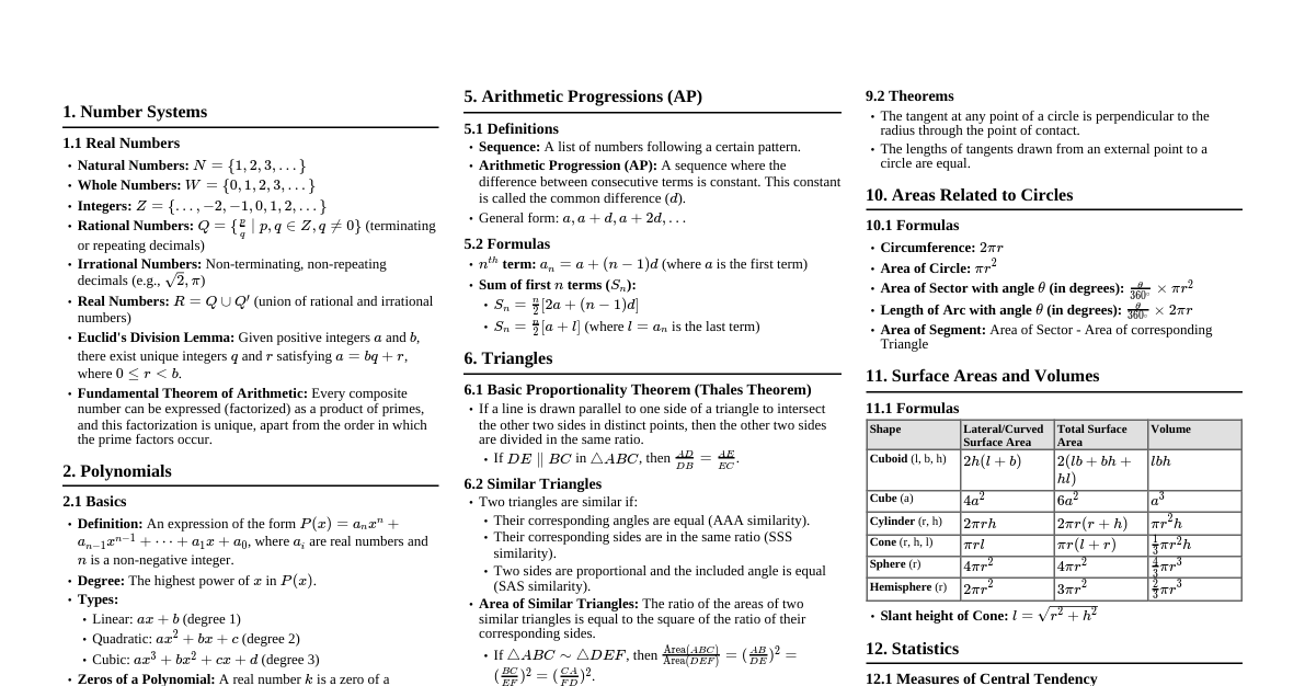
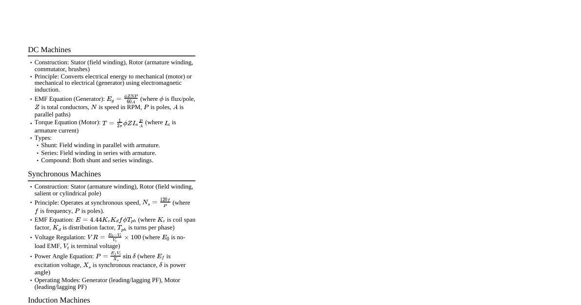
1. Induction Motor 1.1. Basics Principle: Based on electromagnetic induction. Stator magnetic field induces current in rotor. Types: Squirrel Cage (most common), Wound Rotor (slip ring). Slip ($s$): $s = \frac{N_s - N_r}{N_s}$, where $N_s$ is synchronous speed, $N_r$ is rotor speed. Synchronous Speed ($N_s$): $N_s = \frac{120 f}{P}$ (RPM), where $f$ is frequency, $P$ is number of poles. Rotor Frequency ($f_r$): $f_r = s f$. 1.2. Torque Characteristics Starting Torque: $T_{st} \propto (V/f)^2 \cdot R_2 / (R_2^2 + (s X_2)^2)$ (at $s=1$). Maximum Torque (Pull-out Torque): Occurs when $R_2 = s X_2$. $T_{max} \propto (V/f)^2 / (2 X_2)$. Torque-Slip Curve: Low slip: Nearly linear, $T \propto s$. High slip: $T \propto 1/s$. 1.3. Equivalent Circuit Referred to stator: $R_1, X_1$ (stator resistance/reactance), $R_c, X_m$ (core loss/magnetizing reactance), $R_2'/s, X_2'$ (rotor resistance/reactance referred to stator). Air gap power ($P_{ag}$): $P_{ag} = 3 I_2'^2 R_2'/s$. Mechanical power developed ($P_m$): $P_m = P_{ag} (1-s) = 3 I_2'^2 R_2' \frac{1-s}{s}$. Rotor copper loss ($P_{cu,r}$): $P_{cu,r} = s P_{ag}$. 2. Alternators (Synchronous Generators) 2.1. Basics Principle: Converts mechanical energy to AC electrical energy. Construction: Stationary armature (stator) and rotating field (rotor). Synchronous Speed ($N_s$): $N_s = \frac{120 f}{P}$ (RPM). Rotor must rotate at synchronous speed. Generated EMF ($E_f$): $E_f = 4.44 K_p K_d f \phi N_{ph}$, where $K_p$ (pitch factor), $K_d$ (distribution factor), $\phi$ (flux per pole), $N_{ph}$ (turns per phase). 2.2. Equivalent Circuit Per phase: $E_f = V_t + I_a (R_a + j X_s)$, where $V_t$ is terminal voltage, $I_a$ is armature current, $R_a$ is armature resistance, $X_s$ is synchronous reactance. Synchronous Impedance ($Z_s$): $Z_s = R_a + j X_s$. 2.3. Voltage Regulation (VR) $VR = \frac{E_f - V_t}{V_t} \times 100\%$ (at full load, unity PF). Leading PF: VR can be negative (voltage rises). Lagging PF: VR is positive (voltage drops). 2.4. Parallel Operation Conditions: Same voltage magnitude, same frequency, same phase sequence, correct phase angle. Synchronizing: Dark lamp or bright lamp method, synchroscope. Load Sharing: Real Power: Controlled by prime mover's speed-governor characteristic. Reactive Power: Controlled by excitation. 3. Synchronous Motors 3.1. Basics Principle: Converts AC electrical energy to mechanical energy. Operates at synchronous speed. Self-starting: Not inherently self-starting (requires auxiliary starting methods). Power Factor Control: Can operate at leading, lagging, or unity power factor by varying excitation. 3.2. V-Curves Plot of armature current ($I_a$) vs. field current ($I_f$) for constant mechanical power. Minimum $I_a$ at unity power factor. Under-excitation: Lagging PF. Over-excitation: Leading PF (acts as a synchronous condenser). 3.3. Power Developed $P_m = \frac{3 V_t E_f}{X_s} \sin \delta$, where $\delta$ is the power angle. Maximum power occurs at $\delta = 90^\circ$. 4. DC Machines 4.1. DC Generators Principle: Converts mechanical energy to DC electrical energy. EMF Equation: $E_g = \frac{\phi Z N P}{60 A}$, where $\phi$ (flux/pole), $Z$ (total conductors), $N$ (speed in RPM), $P$ (poles), $A$ (parallel paths). Types: Separately Excited: Field winding supplied by external source. $V_t = E_g - I_a R_a$. Self-Excited: Shunt: Field in parallel with armature. $V_t = E_g - I_a R_a$. $I_a = I_L + I_{sh}$. $I_{sh} = V_t / R_{sh}$. Series: Field in series with armature. $V_t = E_g - I_a (R_a + R_{se})$. $I_a = I_L = I_{se}$. Compound: Both shunt and series windings (long/short shunt, cumulative/differential). 4.2. DC Motors Principle: Converts DC electrical energy to mechanical energy. Back EMF ($E_b$): $E_b = \frac{\phi Z N P}{60 A}$. Opposes applied voltage. Voltage Equation: $V_t = E_b + I_a R_a$. Torque Equation: $T_a = \frac{1}{2\pi} \phi Z I_a \frac{P}{A} = K \phi I_a$. Speed Equation: $N \propto \frac{V_t - I_a R_a}{\phi}$. Types: Shunt Motor: Nearly constant speed. Good speed regulation. $N \propto V_t / \phi$. Series Motor: High starting torque. Speed varies widely with load ($N \propto 1/\phi$). Never run at no-load. Compound Motor: Combination of shunt and series characteristics. Speed Control: Flux Control: Varying field current (shunt motor). Armature Voltage Control: Varying $V_t$ applied to armature. Armature Resistance Control: Adding resistance in series with armature. 5. Transformers 5.1. Basics Principle: Transfers electrical energy between circuits through electromagnetic induction, without change in frequency. Construction: Core (laminated steel), primary winding, secondary winding. Ideal Transformer Equations: Voltage Ratio: $\frac{V_1}{V_2} = \frac{N_1}{N_2} = a$ (turns ratio). Current Ratio: $\frac{I_2}{I_1} = \frac{N_1}{N_2} = a$. Power: $V_1 I_1 \cos\phi_1 = V_2 I_2 \cos\phi_2$ (Power in = Power out). EMF Equation: $E = 4.44 f \phi_m N$, where $\phi_m$ is maximum flux. 5.2. Equivalent Circuit Referred to primary: $R_1, X_1$ (primary resistance/reactance), $R_c, X_m$ (core loss/magnetizing reactance), $R_2', X_2'$ (secondary referred resistance/reactance), $R_L'$ (referred load resistance). $R_2' = a^2 R_2$, $X_2' = a^2 X_2$, $Z_L' = a^2 Z_L$. 5.3. Losses Core Losses ($P_c$): Hysteresis and Eddy Current losses. Dependent on voltage and frequency. Copper Losses ($P_{cu}$): $I^2 R$ losses in windings. Dependent on current. 5.4. Efficiency ($\eta$) $\eta = \frac{\text{Output Power}}{\text{Input Power}} = \frac{P_{out}}{P_{out} + P_c + P_{cu}}$. Maximum efficiency occurs when $P_c = P_{cu}$. 5.5. Voltage Regulation (VR) $VR = \frac{V_{2,NL} - V_{2,FL}}{V_{2,FL}} \times 100\%$, where $V_{2,NL}$ is no-load secondary voltage, $V_{2,FL}$ is full-load secondary voltage. Approximate VR: $VR \approx \frac{I_2 (R_{eq2} \cos\phi \pm X_{eq2} \sin\phi)}{V_2}$. (+ for lagging PF, - for leading PF). 5.6. Tests Open Circuit Test: Determines core losses ($P_c$) and magnetizing branch parameters ($R_c, X_m$). Performed at rated voltage, no load. Short Circuit Test: Determines copper losses ($P_{cu}$) and equivalent series parameters ($R_{eq}, X_{eq}$). Performed at reduced voltage, full load current.