AC Power Analysis & Electrical Machines
Cheatsheet Content
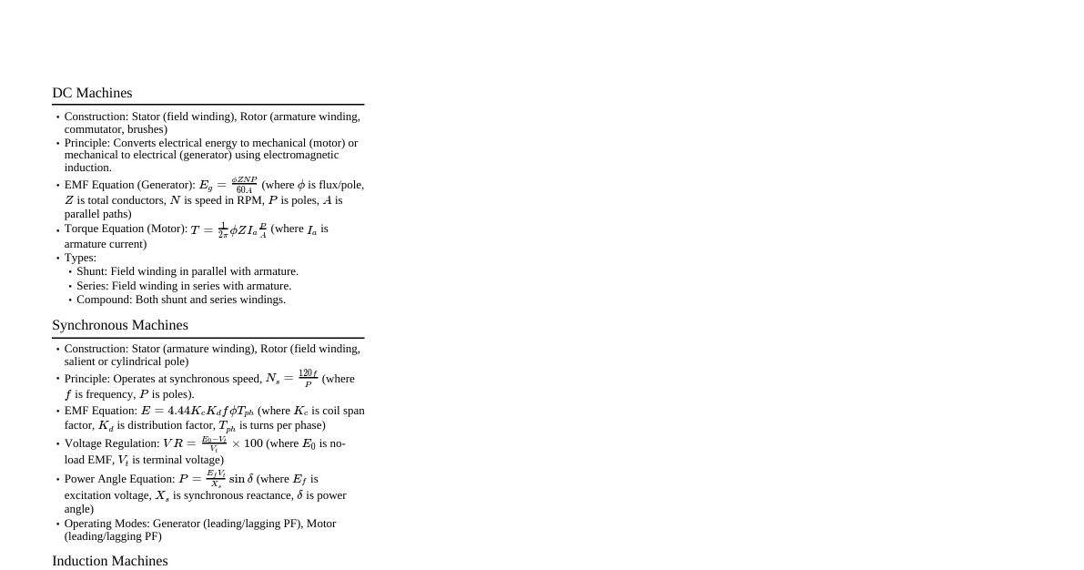
AC Power Analysis Instantaneous and Average Power Instantaneous power $p(t)$ absorbed by an element is the product of instantaneous voltage $v(t)$ and instantaneous current $i(t)$: $p(t) = v(t)i(t)$ For sinusoidal voltage and current: $v(t) = V_m \cos(\omega t + \theta_v)$ $i(t) = I_m \cos(\omega t + \theta_i)$ $p(t) = \frac{1}{2}V_m I_m \cos(\theta_v - \theta_i) + \frac{1}{2}V_m I_m \cos(2\omega t + \theta_v + \theta_i)$ First part: Constant power Second part: Sinusoidal power at $2\omega t$ Average power $P$ (in watts) over one period $T$: $P = \frac{1}{T}\int_0^T p(t) dt = \frac{1}{2}V_m I_m \cos(\theta_v - \theta_i)$ Using phasors: $V = V_m \angle\theta_v$, $I = I_m \angle\theta_i$ $P = \frac{1}{2} \text{Re}[VI^*] = \frac{1}{2}V_m I_m \cos(\theta_v - \theta_i)$ For a resistive load ($\theta_v = \theta_i$): $P = \frac{1}{2}V_m I_m = \frac{1}{2}I_m^2 R = \frac{1}{2} \frac{V_m^2}{R}$ For a reactive load ($\theta_v - \theta_i = \pm 90^\circ$): $P = \frac{1}{2}V_m I_m \cos(90^\circ) = 0$ Effective or RMS Value Effective value of a periodic current $i(t)$: $I_{eff} = \sqrt{\frac{1}{T}\int_0^T i^2(t) dt}$ Effective value of a periodic voltage $v(t)$: $V_{eff} = \sqrt{\frac{1}{T}\int_0^T v^2(t) dt}$ For sinusoidal signals: $I_{rms} = I_{eff} = \frac{I_m}{\sqrt{2}}$ $V_{rms} = V_{eff} = \frac{V_m}{\sqrt{2}}$ Average power in terms of RMS values: $P = V_{rms} I_{rms} \cos(\theta_v - \theta_i)$ $P = I_{rms}^2 R = \frac{V_{rms}^2}{R}$ Apparent Power and Power Factor Apparent Power $S$: The product of the RMS values of voltage and current, measured in Volt-Amperes (VA). $S = V_{rms} I_{rms}$ Power Factor (pf): Dimensionless ratio of average power to apparent power. $pf = \frac{P}{S} = \cos(\theta_v - \theta_i)$ Power factor depends on the phase difference between voltage and current: Load Type Phase Angle $\theta_v - \theta_i$ Power Factor (pf) Purely resistive (R) $0$ $1$ (unity pf) Purely reactive (L or C) $\pm 90^\circ$ $0$ Resistive and inductive (R, L) $>0$ Lagging pf Resistive and capacitive (R, C) $ Leading pf Complex Power Complex Power $S$: The product of the RMS voltage phasor and the complex conjugate of the RMS current phasor. $S = V_{rms} I_{rms}^* = P + jQ$ $S = V_{rms} I_{rms} \angle(\theta_v - \theta_i)$ Real Power $P$ (Average Power): Represents the actual power dissipated by the load (in watts). $P = \text{Re}(S) = V_{rms} I_{rms} \cos(\theta_v - \theta_i)$ Reactive Power $Q$: Represents the energy exchange between the source and the reactive part of the load (in VAR). $Q = \text{Im}(S) = V_{rms} I_{rms} \sin(\theta_v - \theta_i)$ Magnitude of complex power is apparent power: $|S| = \sqrt{P^2 + Q^2} = V_{rms} I_{rms}$ Complex power in terms of impedance $Z = R + jX$: $S = I_{rms}^2 Z = I_{rms}^2 (R + jX) = P + jQ$ $P = I_{rms}^2 R$ $Q = I_{rms}^2 X$ Power Triangle: $P$: horizontal axis $Q$: vertical axis $S$: hypotenuse Angle $\theta_v - \theta_i$: angle between $P$ and $S$. Reactive Power $Q$ characteristics: $Q=0$: Resistive loads (unity pf) $Q $Q>0$: Inductive loads (lagging pf) Conservation of AC Power The complex power supplied by a source equals the sum of the complex powers delivered to the individual loads. $S_{source} = \sum_{k=1}^N S_k$ Similarly, for real and reactive powers: $P_{source} = \sum_{k=1}^N P_k$ $Q_{source} = \sum_{k=1}^N Q_k$ Electrical Machines Types of Electrical Machines Electro-Mechanical Energy Conversion devices that convert electrical energy into mechanical energy and vice-versa. Categories: DC Machines: DC Motors, DC Generators (Series, Shunt, Compound) AC Machines: AC Motors (Induction, Synchronous), AC Generators, Transformers (1-Phase, 3-Phase, Auto) How Electrical Machines Work Two electromagnetic conversion phenomena: Induced voltage (Generator action): When a conductor moves in a magnetic field, voltage is induced in the conductor. Force and developed torque (Motor action): When a current-carrying conductor is placed in a magnetic field, it experiences a mechanical force. Force on conductor carrying current $I$ in field $B$: $F = I B l$ Voltage (emf) induced in conductor traveling with velocity $v$ in field $B$: $e = v B l$ Rotating Electrical Machines Stator: Fixed part, normally sets up the magnetic field. Rotor: Rotating part, normally carries currents (either supplied or induced) and experiences torque. Current $I$ flows in rotor, Force $F=IB$, Torque $T=Fr$. EMF Induced in DC Motor Induced EMF $E = N v B l = k \omega$ $E$ is proportional to angular velocity $\omega$. Equivalent circuit for a separately excited DC motor includes armature resistance $R_a$, field resistance $R_f$, and applied voltages $V_a, V_f$. Characteristics of DC Machine Field $B$ is normally constant. Torque $T = k i_f i_a$. Armature current $i_a$ controls torque. Requires carbon brushes (sparking, wear, maintenance). Expensive due to commutator and armature winding construction. Common for small motors (permanent magnet field). "Universal motor": Armature and field winding in series, run directly off single-phase AC mains (e.g., in household appliances). Three-Phase Induction Motors "Workhorse of Industry": Simple design, rugged, low-price, easy maintenance. Wide range of power ratings (fractional horsepower to 10 MW). Runs essentially at constant speed from no-load to full-load. Speed depends on supply frequency. Variable speed control requires variable-frequency power-electronic drive. Induction Motor Construction Stator: Stationary part, steel frame supporting a hollow, cylindrical core. Core made of stacked laminations with slots for stator winding. Three-phase stator winding (Star or Delta connected, Copper conductors). Rotor: Revolving part, composed of punched laminations with rotor slots. Two basic types: Squirrel-cage rotor: Conducting bars laid into slots and shorted at both ends by shorting rings. Simple, rugged. Wound-rotor (Slip-Ring Rotor): Conventional 3-phase windings (usually Y-connected) with ends connected to slip rings on the rotor shaft. Allows external resistance insertion. Advantages of Slip Ring Induction Motor Speed can be controlled easily. High starting torque (200-250% of full-load torque). Low starting current (250-350% of full-load current, compared to 600-700% for squirrel-cage). Useful for starting heavy loads (cranes, conveyors). Disadvantages of Slip Ring Induction Motor Higher initial and maintenance cost (slip rings, brushes, short circuiting devices). Poor speed regulation with external resistances. Lower efficiency and power factor. Sensitivity to fluctuations in supply voltage. How Magnetic Field B is Produced Electrical frequency $\omega_e = 2\pi f_e$ elec. rads/s. Magnetic field $B$ rotates in space at $\omega_s = \frac{2}{P}\omega_e$ mech. rads/s. Synchronous speed ($n_{sync}$): The speed at which the rotating magnetic field rotates. $n_{sync} = \frac{120 f_e}{P}$ rpm $f_e$: supply frequency (Hz) $P$: number of poles The greater the number of poles, the slower the synchronous speed. Stator windings of an Induction Machine (IM) are wound for a fixed number of poles. Rotating Magnetic Field Balanced three-phase windings, mechanically displaced by $120^\circ$, fed by a balanced three-phase source, produce a rotating magnetic field of constant magnitude. Induction Motor Speed An IM always runs at a speed lower than the synchronous speed. Slip ($n_{slip}$): The difference between the synchronous speed and the rotor mechanical speed. $n_{slip} = n_{sync} - n_m$ $n_{sync}$: speed of magnetic field (rpm) $n_m$: mechanical shaft speed of motor (rpm) If the rotor runs at synchronous speed ($n_m = n_{sync}$), the magnetic field does not cut the rotor, no induced current flows, no torque is generated, and the rotor speed falls. When speed falls, the magnetic field cuts rotor windings, generating torque. The Slip (s) Ratio of slip speed to synchronous speed: $s = \frac{n_{sync} - n_m}{n_{sync}}$ If rotor runs at synchronous speed ($n_m = n_{sync}$), then $s = 0$. If rotor is stationary ($n_m = 0$), then $s = 1$. Slip can be expressed as a percentage by multiplying by 100. Induction Motors and Transformers Both work on the principle of induced voltage. Transformer: Voltage applied to primary windings induces voltage in secondary windings. Induction Motor: Voltage applied to stator windings induces voltage in rotor windings. Difference: In IM, secondary (rotor) windings can move. Due to rotor rotation, induced voltage in rotor does not have the same frequency as stator voltage. Frequency of Rotor Induced Voltage The frequency of the voltage induced in the rotor ($f_r$) is given by: $f_r = \frac{P \times n_{slip}}{120} = s f_e$ $f_r$: rotor frequency (Hz) $P$: number of stator poles $n_{slip}$: slip speed (rpm) $s$: slip $f_e$: supply frequency (Hz) If rotor is blocked ($s=1$), $f_r = f_e$. If rotor runs at synchronous speed ($s=0$), $f_r = 0$. Torque Output mechanical power is $P_{out}$. Mechanical load applied to motor shaft introduces torque $\tau_{load}$. Relationship between torque, output power, and rotor speed: $\tau_{load} = \frac{P_{out}}{\omega_m}$ N.m $\omega_m = \frac{2\pi n_m}{60}$ rad/s $\omega_m$: mechanical angular speed of rotor $n_m$: mechanical shaft speed of motor (rpm) Horsepower (HP): Another unit for mechanical power. $1 \text{ HP} = 746 \text{ watts}$. Torque-Speed Characteristics Synchronous speed: Induced torque is zero. No-load to full-load: Torque-speed curve is nearly linear. Rotor resistance is much greater than reactance, so rotor current and torque increase linearly with slip. Pullout torque: Maximum possible torque, typically 2-3 times the rated full-load torque. Starting torque: Slightly higher than full-load torque, allowing the motor to start with load. Torque varies as the square of the applied voltage. If rotor is driven faster than synchronous speed, it acts as a generator, converting mechanical power to electric power. Speed Control of Induction Motors Frequency Control: Most popular. Changes supply frequency using an inverter, affecting synchronous speed $n_{sync} = \frac{120 f_e}{P}$. Voltage Control: Reduces speed by decreasing applied voltage (e.g., using Thyristor voltage controller or Autotransformer). Suitable for loads where torque decreases with speed. Pole Changing: Changes the number of stator poles, providing discrete speed steps. Rotor Resistance Control (for Wound-Rotor IMs): Adding external resistance to rotor circuit via slip rings controls speed. Not applicable for squirrel-cage motors. Slip Power Recovery (for Wound-Rotor IMs): Recovers energy from rotor circuit slip, improving efficiency at speeds below synchronous speed. Applications of Induction Motors Industrial: Pumps, fans, compressors, conveyors, automated machinery, HVAC systems, specialized equipment (printing, etc.). Residential: Household appliances (washing machines, AC, refrigerators). Transportation: Electric vehicles (EVs) for high torque and efficiency. Energy Generation: Wind turbines (as generators). Transformers Introduction Invented by William Stanley in 1885. Static device for transferring electrical energy between circuits without changing frequency. Used to change AC voltage levels. Works based on Faraday's law of Electro Magnetic Induction. Components: Winding: Primary and Secondary (Copper/Aluminium conductors). Magnetic Core: Iron core (magnetic circuit). Windings are magnetically coupled but electrically isolated. General Structure of Electrical Power System Generation $\rightarrow$ Step-Up Transformer (e.g., 12 kV to 400 kV) $\rightarrow$ High-voltage Transmission Lines $\rightarrow$ Step-down Transformer (substation, e.g., 400 kV to 132 kV) $\rightarrow$ Distribution Lines $\rightarrow$ Step-down Transformer (consumer, e.g., 11 kV to 240 V). Transformer Components Magnetic Core: Made of high-grade silicon steel or sheet steel laminations. Low hysteresis loss, continuous magnetic path. Functions: Provides low reluctance path for flux, carries windings. Electric Circuit (Windings): Primary winding: Connected to input side. Secondary winding: Connected to output side. Made of copper. Types of Transformer (based on core construction) Core-type: Windings surround the core limbs. Lamination cut in L, I, or U strips. More copper, two limbs. More insulation, equal flux distribution. Two magnetic circuits, more leakage flux. Easy to maintain, high output. Shell-type: Core surrounds a considerable portion of windings, placed on central limb. Lamination cut in long E and I strips. Less copper, three limbs. Less insulation, unequal flux distribution. One magnetic circuit, less loss. Difficult to maintain, less output. EMF Equation of a Transformer Flux $\Phi = \Phi_m \sin(\omega t)$ Induced EMF in primary winding $E_1 = -N_1 \frac{d\Phi}{dt} = -N_1 \omega \Phi_m \cos(\omega t)$ RMS value of induced EMF: $E_1 = 4.44 f N_1 \Phi_m$ volts $E_2 = 4.44 f N_2 \Phi_m$ volts $f$: frequency (Hz) $N_1, N_2$: number of turns in primary/secondary $\Phi_m$: maximum flux in core (Wb) Transformation Ratio (K) Ratio of secondary to primary EMFs, or turns: $K = \frac{E_2}{E_1} = \frac{N_2}{N_1}$ If $K > 1$: Step-up transformer ($E_2 > E_1, N_2 > N_1$). If $K If $K = 1$: Isolation transformer ($E_2 = E_1, N_2 = N_1$). Assuming primary side power equals secondary side power: $E_1 I_1 = E_2 I_2 \Rightarrow \frac{I_1}{I_2} = \frac{E_2}{E_1} = K$ Ideal Transformer on No-load Properties: Absence of winding resistance, infinite permeability of core, no leakage flux, 100% efficiency. Magnetizing current ($I_m$) drawn from source to produce flux. $I_m$ lags $V_1$ by $90^\circ$. Alternating flux $\Phi$ is in phase with $I_m$. $\Phi$ induces $E_1$ (opposing $V_1$) and $E_2$ in secondary. Secondary current $I_2 = 0$ as circuit is open. Practical Transformer on No-load Primary current has two components: Magnetizing component ($I_m$): Purely reactive, lags $V_1$ by $90^\circ$. Loss component ($I_c$): Supplies core losses. In phase with $V_1$. No-load current $I_0$ is vector sum of $I_m$ and $I_c$. $I_0$ is small (approx. 0.04 times full-load current). Core loss is significant, primary copper loss is negligible. Secondary circuit remains open ($I_2 = 0$). Losses in Transformer Core losses (Iron losses): Occur due to alternating flux in core. Hysteresis loss Eddy current loss Copper losses: Occur due to current flowing in windings (resistive losses). Primary copper loss Secondary copper loss Note: Copper loss depends on current ($I^2$), Core loss depends on voltage ($V$). Efficiency of Transformer ($\eta$) Ratio of power output to power input. $\eta = \frac{\text{Output}}{\text{Input}} = \frac{\text{Output}}{\text{Output} + \text{Losses}}$ $\eta = \frac{\text{Output}}{\text{Output} + \text{Cu loss} + \text{Iron loss}}$ Efficiency at any load $x$ (fraction of full-load kVA, $0 $\eta = \frac{x \times \text{Full-load kVA} \times pf}{(x \times \text{Full-load kVA} \times pf) + W_{cu} + W_i} \times 100\%$ $W_{cu}$: Full-load copper loss $W_i$: Iron loss Transformer efficiency is maximum when copper loss equals core loss ($W_{cu} = W_i$). Applications of Transformers Power Generation: Step-up voltage in power plants for transmission. Power Distribution: Step-down voltage for local distribution. Electronics: Used in almost all electronic circuits. Measurement: Potential transformers (PTs) for high voltage, Current transformers (CTs) for high current. Specialized: Furnace transformers, welding transformers. Power Distribution Example: Generation (16 kV) $\rightarrow$ Step-up (16/66 kV) $\rightarrow$ Transmission (66/275 kV, 200 km) $\rightarrow$ Step-down (275/66 kV) $\rightarrow$ Distribution (66/11 kV) $\rightarrow$ Local step-down (11 kV/415 V or 240 V). Isolation and Safety No electrical connection between primary and secondary circuits. Secondary circuit is "electrically isolated" from primary. Important for safety (e.g., in case of ground faults). Ratings Specified in kVA (apparent power), primary/secondary voltages, and frequency. Example: 240/15V, 150 VA, 50 Hz. 240 V: Rated input voltage 15 V: Full load output voltage ($V_2$) 50 Hz: Designed frequency 150 VA: Volt-Amp rating ($V_2 I_2$ RMS values) Rating indicates maximum power delivered without exceeding permissible temperature rise. Good Transformer Characteristics High permeability core (low magnetizing current). Low iron losses (laminated core, silicon steel/soft ferrite). Small leakage reactance (primary and secondary coils on top of each other). Low winding resistances (reduced $I^2R$ loss, higher efficiency). Good conductors (aluminum, copper) and heavier insulation.