Electrical Machines Exam
Cheatsheet Content
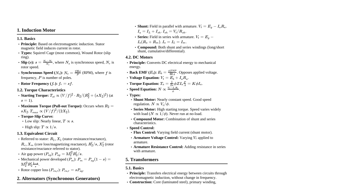
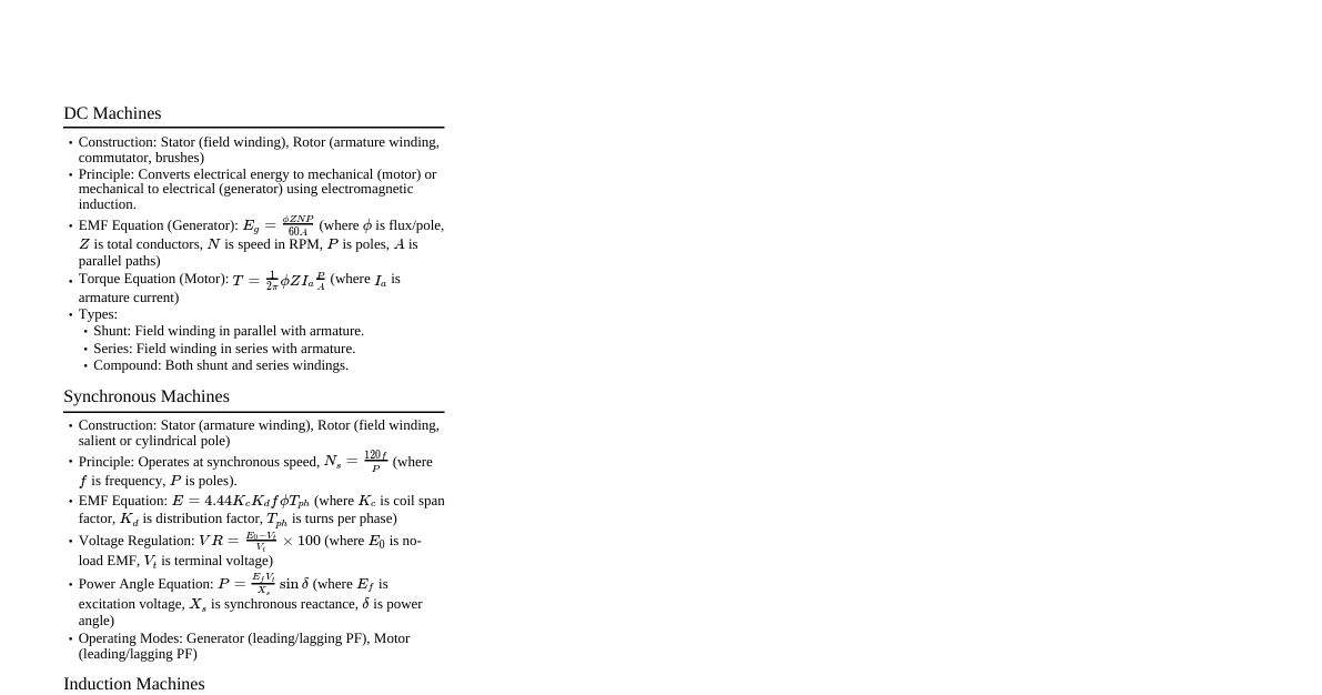
### DC Motor Torque Equation & Types - **Torque Equation:** The torque ($T$) developed in a DC motor is directly proportional to the armature current ($I_a$) and the magnetic flux ($\Phi$). $$T = k \Phi I_a$$ Where $k$ is a constant. - **Difference between DC Shunt and Series Motor:** | Feature | DC Shunt Motor | DC Series Motor | |---------------|----------------------------------------------------|-------------------------------------------------------| | Field Winding | Connected in parallel with armature (high resistance) | Connected in series with armature (low resistance) | | Flux ($\Phi$) | Relatively constant, independent of load | Varies directly with armature current and thus load | | Speed | Nearly constant speed characteristic | Highly variable speed, decreases sharply with load | | Starting Torque | Moderate starting torque | Very high starting torque | | Applications | Lathes, centrifuges, pumps, fans | Cranes, hoists, electric trains, vacuum cleaners | ### Two Reaction Theory in Salient Pole Synchronous Machine - **Definition:** The two-reaction theory simplifies the analysis of salient pole synchronous machines by resolving the armature MMF into two components: 1. **Direct-axis component ($F_d$):** Acts along the axis of the main field poles. 2. **Quadrature-axis component ($F_q$):** Acts perpendicularly to the direct axis, in the interpolar region. - **Purpose:** Due to the non-uniform air gap in salient pole machines, the magnetic reluctance is different along the direct and quadrature axes. This theory allows for separate analysis of reactances ($X_d$ and $X_q$) along these axes. - **Impact:** $X_d \ne X_q$, which leads to reluctance torque in addition to excitation torque. ### DC Motor Starter & Three-Point Starter - **Why use a starter?** - At starting, the back EMF ($E_b$) is zero. - The armature resistance ($R_a$) is very low. - If full supply voltage is applied, a very high starting current ($I_a = V/R_a$) would flow, potentially damaging the armature winding and commutator. - A starter limits the initial current by inserting external resistance in series with the armature, which is gradually cut out as the motor speeds up and $E_b$ builds. - **Three-Point Starter:** - **Connections:** It has three terminals: 1. **L (Line):** Connected to the positive supply. 2. **A (Armature):** Connected to the armature winding. 3. **F (Field):** Connected to the shunt field winding. - **Components:** - **Starting resistance:** Series resistors to limit starting current. - **No-volt release (NVR) coil:** Connected in series with the shunt field, holds the handle in the 'run' position. If supply fails, NVR de-energizes, releasing the handle to 'off'. - **Overload release (OLR) coil:** Protects against excessive load current. If current exceeds a safe limit, OLR trips the handle to 'off'. - **Operation:** The operator moves the handle from 'off' to 'run' position, gradually cutting out resistance. ### Characteristics of Different Types of DC Motors - **Speed-Armature Current ($N-I_a$) and Torque-Armature Current ($T-I_a$) Characteristics** - **DC Shunt Motor:** - **$N-I_a$:** Speed drops slightly with increasing load (armature current) due to armature voltage drop. Nearly constant speed. - **$T-I_a$:** Torque is almost directly proportional to armature current ($T \propto I_a$). - **DC Series Motor:** - **$N-I_a$:** Speed is inversely proportional to armature current. Very high speed at light loads, drops sharply with increasing load. Dangerous at no load. - **$T-I_a$:** Torque is proportional to the square of armature current ($T \propto I_a^2$) at low saturation, then becomes proportional to $I_a$ at high saturation. Very high starting torque. - **DC Compound Motor:** (Not explicitly asked but good to know for comparison) - **Cumulative Compound:** Characteristics lie between shunt and series motors. Good starting torque and reasonably constant speed. - **Differential Compound:** Speed increases with load (unstable, rarely used). ### Output Complex Power in Salient Pole Synchronous Machine - **Complex Power ($S$):** The output complex power per phase of a synchronous machine is given by: $$S = P + jQ = V_t I_a^*$$ Where $V_t$ is the terminal voltage and $I_a^*$ is the conjugate of the armature current. - **In terms of $V_t$, $E_f$, $X_d$, $X_q$, and $\delta$ (power angle):** $$P = \frac{E_f V_t}{X_d} \sin\delta + V_t^2 \left( \frac{X_d - X_q}{2 X_d X_q} \right) \sin(2\delta)$$ $$Q = \frac{E_f V_t}{X_d} \cos\delta - V_t^2 \left( \frac{1}{X_q} + \frac{1}{X_d} \right) \frac{1}{2} + V_t^2 \left( \frac{X_d - X_q}{2 X_d X_q} \right) \cos(2\delta)$$ - The first term in $P$ is the excitation power, and the second term is the reluctance power (due to saliency). - $E_f$: Excitation voltage (proportional to field current). - $X_d$: Direct-axis synchronous reactance. - $X_q$: Quadrature-axis synchronous reactance. - $\delta$: Power angle or torque angle. ### Armature Reaction and Synchronous Motor Types - **Armature Reaction in Synchronous Motor:** The effect of armature magnetic flux on the main field flux. It depends on the power factor and load condition. - **Unity Power Factor (Resistive Load):** Cross-magnetizing effect. Armature MMF is at 90 degrees to field MMF, distorting the main field. - **Lagging Power Factor (Inductive Load):** Demagnetizing effect. Armature MMF opposes the main field MMF, reducing the net flux. - **Leading Power Factor (Capacitive Load):** Magnetizing effect. Armature MMF aids the main field MMF, increasing the net flux. - **Difference between Cylindrical (Round Rotor) and Salient Pole Synchronous Motor:** | Feature | Cylindrical (Round Rotor) | Salient Pole Rotor | |---------------|----------------------------------------------|-----------------------------------------------------------| | Rotor Shape | Smooth, cylindrical, uniform air gap | Projecting poles, non-uniform air gap | | Poles | Non-projecting, distributed winding | Projecting poles, concentrated winding | | Reactance | $X_d = X_q$ (uniform reluctance) | $X_d \ne X_q$ (different reluctance along axes) | | Reluctance Torque | No reluctance torque | Significant reluctance torque | | Speed | High speed (e.g., turbo-generators) | Low to medium speed (e.g., hydro-generators, compressors) | | Diameter/Length | Small diameter, long axial length | Large diameter, short axial length | ### Circuit Diagram of Different Types of DC Motors - **DC Shunt Motor:** - Armature winding in parallel with shunt field winding. - Field current is constant, independent of load. *Note: The provided image is a general question paper, not a circuit diagram. A proper circuit diagram would show the armature and field windings.* - **DC Series Motor:** - Armature winding in series with series field winding. - Field current is same as armature current, varies with load. *Note: The provided image is a general question paper, not a circuit diagram. A proper circuit diagram would show the armature and field windings.* - **DC Compound Motor:** - Has both shunt and series field windings. - **Short Shunt:** Shunt field is parallel to armature only. - **Long Shunt:** Shunt field is parallel to the series combination of armature and series field. *Note: The provided image is a general question paper, not a circuit diagram. A proper circuit diagram would show the armature and field windings.* ### Phasor Diagram of Salient Pole Synchronous Machine - **Assumptions:** Generator convention, neglecting armature resistance ($R_a \approx 0$). - **Key Phasors:** - $V_t$: Terminal voltage (reference phasor). - $I_a$: Armature current. - $E_f$: Excitation voltage. - $I_d$: Direct-axis component of $I_a$. - $I_q$: Quadrature-axis component of $I_a$. - $j I_d X_d$: Voltage drop due to direct-axis reactance. - $j I_q X_q$: Voltage drop due to quadrature-axis reactance. - **Construction:** 1. Draw $V_t$ as the reference phasor on the real axis. 2. Draw $I_a$ at an angle $\phi$ (lagging or leading $V_t$). 3. Resolve $I_a$ into $I_d$ (in phase with $E_f$ and perpendicular to $V_t$ for generator) and $I_q$ (perpendicular to $I_d$). 4. Draw $j I_q X_q$ perpendicular to $I_q$. 5. Draw $j I_d X_d$ perpendicular to $I_d$. 6. The phasor sum $V_t + j I_q X_q + j I_d X_d = E_f$. - The angle between $V_t$ and $E_f$ is the power angle $\delta$. *Note: The provided image is a general question paper, not a phasor diagram. A proper phasor diagram would illustrate the vector relationships.* ### Zero Power Characteristics in Synchronous Machine - **Zero Power Factor (ZPF) Characteristics:** Also known as the Potier diagram or ZPF saturation curve. - **Purpose:** Used to determine the synchronous reactance ($X_s$) and armature reaction MMF (or Potier reactance $X_p$) of a synchronous machine. - **How it's obtained:** 1. The machine is operated at rated speed. 2. The armature is short-circuited through an ammeter to get the short-circuit characteristic (SCC) curve. 3. The machine is operated at leading zero power factor (purely capacitive load or underexcited operation) while maintaining rated terminal voltage. The field current is varied, and the corresponding armature current is recorded. - **Significance:** At ZPF leading, the armature reaction is purely magnetizing, and at ZPF lagging, it's purely demagnetizing. This helps in separating the components of synchronous impedance. ### Working of Salient Pole Synchronous Machine - **Principle:** Operates on the principle of magnetic locking between the rotating magnetic field produced by the stator (armature) and the magnetic poles of the rotor (field winding). - **Construction:** - **Stator:** Houses the armature winding, which is usually a 3-phase winding. - **Rotor:** Salient poles with concentrated DC field windings. These poles are excited by a DC source. - **Operation (Generator Mode):** 1. The rotor is mechanically driven by a prime mover (e.g., turbine) at synchronous speed. 2. The rotating DC field flux cuts the stator conductors, inducing a 3-phase EMF in the stator windings (Faraday's Law of Electromagnetic Induction). 3. When connected to a load, armature current flows, creating an armature MMF. 4. The interaction between the rotor field MMF and the stator armature MMF determines the power angle and the output power. 5. Due to salient poles, reluctance torque is also produced, which contributes to the total torque along with the excitation torque. - **Operation (Motor Mode):** 1. The stator is supplied with a 3-phase AC voltage, creating a rotating magnetic field (RMF) at synchronous speed. 2. The rotor field winding is excited with DC, creating fixed magnetic poles. 3. To start, the motor needs an external prime mover or damper windings to bring it close to synchronous speed. 4. Once near synchronous speed, the rotor poles lock with the stator RMF, and the motor pulls into synchronism, rotating at synchronous speed. 5. The interaction of the two magnetic fields produces the torque. - **Key Characteristics:** - Constant speed operation (synchronous speed). - Can operate at leading, lagging, or unity power factor by varying field excitation. - Has reluctance torque in addition to excitation torque due to saliency.