Computer Networks Essentials
Shared 3/30/2026•112 views
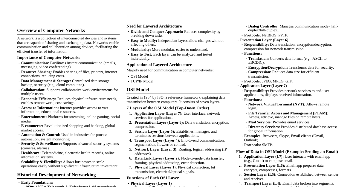
### OSI Reference Model The Open Systems Interconnection (OSI) model is a conceptual framework for understanding network architectures, developed by ISO. It ensures different systems can communicate regardless of hardware/software. #### Core Purposes - **Interoperability:** Allows products from different vendors to work together. - **Modular Development:** Developers can focus on specific layers independently. - **Troubleshooting:** Provides a structured map for diagnosing network issues. - **Education:** Simplifies learning networking by dividing it into functional pieces. #### The Seven Layers | Layer | Name | Primary Function | | :--- | :--- | :--- | | **7** | Application | Network services for user applications (HTTP, FTP, SMTP). | | **6** | Presentation | Data translation, encryption, and compression. | | **5** | Session | Managing and terminating connections between applications. | | **4** | Transport | End-to-end communication and error recovery (TCP, UDP). | | **3** | Network | Determining the best physical path for data (IP Addressing, Routing). | | **2** | Data Link | Error-free transfer of data frames between two nodes (MAC addresses). | | **1** | Physical | Transmission of raw bitstreams over a physical medium (Cables, Hubs). | **Key Concept: Data Encapsulation:** As data moves down the layers, each layer adds its own "header." At the receiver, headers are stripped off layer by layer. ### TCP/IP Model The TCP/IP (Transmission Control Protocol/Internet Protocol) model is a concise, four-layer conceptual framework that serves as the foundation for the modern internet. #### Key Characteristics - **End-to-End Connectivity:** Ensures data reaches the correct destination. - **Robustness:** Reliable; data can often be rerouted even if parts of the network fail. - **Standardization:** The protocol suite used by every device connected to the internet. #### The Four Layers of TCP/IP | Layer | Name | Primary Function | Key Protocols | | :--- | :--- | :--- | :--- | | **4** | Application | Provides node-to-node communication and controls user-interface specifications. | HTTP, HTTPS, FTP, SMTP, DNS | | **3** | Transport | Responsible for end-to-end communication, flow control, and error correction. | TCP (Reliable), UDP (Fast) | | **2** | Internet | Handles logical addressing (IP) and routing of packets across networks. | IPv4, IPv6, ICMP, ARP | | **1** | Network Access | Defines how data is physically sent through the network hardware. | Ethernet, Wi-Fi, Token Ring | #### Detailed Layer Breakdown 1. **Network Access Layer (Link Layer):** Combines OSI Physical and Data Link. Manages hardware-specific details (MAC addresses, signal conversion). 2. **Internet Layer:** The "heart" of the model. Responsible for **Routing** (finding the best path) using IP addresses. 3. **Transport Layer:** Ensures data packets arrive in correct order and without errors. - **TCP:** Reliability critical (e.g., webpages). Uses three-way handshake. - **UDP:** Speed critical (e.g., video streaming). 4. **Application Layer:** Users interact with this layer. Contains high-level protocols (HTTP, SMTP). #### TCP/IP vs. OSI Model OSI is a 7-layer theoretical guide; TCP/IP is a 4-layer practical implementation. OSI Session/Presentation functions are in TCP/IP Application layer, and OSI Physical/Data Link are in TCP/IP Network Access. ### Transmission Media Transmission media refers to the physical path through which data is transmitted. It is at the **Physical Layer (Layer 1)** of both the OSI and TCP/IP models. #### 1. Guided Media (Wired/Bounded Media) Uses physical conductors to guide electromagnetic waves. - **A. Twisted Pair Cable:** Two insulated copper wires twisted to reduce crosstalk. - **UTP:** Common in Ethernet (RJ45). - **STP:** Metal foil for better noise protection. - **Usage:** LANs, telephone lines. - **B. Coaxial Cable:** Central copper conductor, insulator, braided shield. - **Advantage:** High bandwidth, better noise immunity than twisted pair. - **Usage:** Cable TV, traditional Ethernet. - **C. Fiber Optic Cable:** Transmits data as **pulses of light** through glass/plastic strands, using **Total Internal Reflection**. - **Advantage:** Extremely high bandwidth, immune to EMI, long distances. - **Usage:** Backbone networks, high-speed internet. #### 2. Unguided Media (Wireless/Unbounded Media) Transmits electromagnetic waves without physical conductors (through air, vacuum, water). - **A. Radio Waves:** Omnidirectional, low-frequency, penetrate walls. - **Usage:** AM/FM radio, cordless phones. - **B. Microwaves:** Travel in **straight lines** (unidirectional), require "Line of Sight" (LoS). - **Terrestrial Microwave:** Parabolic antennas on towers. - **Satellite Microwave:** Satellite in orbit as relay station. - **C. Infrared:** High-frequency, very short-range, cannot penetrate walls. - **Usage:** TV remote controls, wireless mice. #### Summary Comparison Table | Feature | Guided Media | Unguided Media | | :--- | :--- | :--- | | **Medium** | Physical cables (Copper/Fiber) | Free space (Air/Vacuum) | | **Signal Direction** | Contained within the cable | Broadcast in all directions | | **Interference** | Low (Shielding protects it) | High (Susceptible to weather/noise) | | **Cost** | Generally higher (Installation/Material) | Lower (No cabling required) | | **Range** | Limited by cable length | Can be global (via Satellite) | ### Error Correction and Detection Errors can occur during data transmission. The **Data Link Layer** and **Transport Layer** use techniques to ensure data integrity. #### 1. Parity Check (Error Detection) Simplest mechanism. A **parity bit** is added to each data unit. - **Even Parity:** Total number of 1s (including parity) must be even. - **Odd Parity:** Total number of 1s must be odd. - **Limitation:** Only detects **single-bit errors**. Fails if two bits are flipped. #### 2. Checksum (Error Detection) Commonly used at the **Transport Layer**. Data is divided into fixed-sized segments. - **Sender:** Segments are added using 1's complement arithmetic. The result is complemented to create the "checksum." - **Receiver:** Adds all segments including checksum. If result is all 1s (or 0 after final complement), data is accepted. - **Usage:** More robust than parity, but can fail if errors cancel each other. #### 3. Cyclic Redundancy Check - CRC (Error Detection) Powerful method based on **binary division**, widely used in Ethernet and Wi-Fi. - **Process:** 1. Append $n$ zeros to data (where $n$ is one less than divisor length). 2. Divide data by a predefined **generator polynomial** using **CRC (Modulo-2) division**. 3. The remainder is the **CRC bits**. 4. Replace zeros with CRC bits. - **Receiver:** Divides entire unit by same divisor. If remainder is **zero**, data is error-free. #### 4. Hamming Code (Error Correction) Can both **detect and correct** errors by identifying the exact position of the corrupted bit. - **Redundant Bits ($r$):** Extra bits placed at specific positions (powers of 2: 1, 2, 4...). $$2^r \ge m + r + 1$$ *(where $m$ is the number of data bits)*. - **Parity Calculation:** Each redundant bit $r$ is a parity bit for a specific combination of data bits. - **Correction:** Failed parity checks generate a binary number pointing to the exact **bit position** of the error, which is then flipped. #### Summary Comparison Table | Method | Type | Complexity | Efficiency | | :--- | :--- | :--- | :--- | | **Parity Check** | Detection | Very Low | Only detects single-bit errors. | | **Checksum** | Detection | Medium | Good for software-based protocols (IP/TCP). | | **CRC** | Detection | High | Most reliable for hardware-level detection. | | **Hamming Code** | Correction | Very High | Can fix errors without retransmission. | ### Sliding Window Protocols In the Data Link Layer, these protocols provide efficient flow control and error control by allowing the sender to transmit multiple frames before needing an acknowledgment (ACK). #### 1. Concept of Sliding Window A "window" is a logical range of sequence numbers. - **Sender Window:** Frames the sender can send without waiting for an ACK. - **Receiver Window:** Frames the receiver is prepared to accept. As ACKs are received, the window "slides" forward, ensuring the link is kept busy and increasing throughput. #### 2. Key Mechanisms - **A. Sequence Numbers:** Each frame assigned a unique sequence number (0 to $2^n - 1$ for an $n$-bit field). - **B. Flow Control:** Window size ($W$) prevents sender from overwhelming receiver. - **C. Pipelining:** Multiple frames can be "in the pipe" (in transit) simultaneously, improving over Stop-and-Wait. #### 3. Types of Sliding Window Protocols - **1. Go-Back-N (GBN):** - Sender Window Size: $N = 2^n - 1$. - Receiver Window Size: Always 1. - **Mechanism:** Receiver only accepts in-order frames. If a frame is lost, receiver discards subsequent frames. Sender retransmits all frames from the lost one ("goes back N"). - **Efficiency:** High in low-error, but wasteful in high-error environments. - **2. Selective Repeat (SR):** - Sender Window Size: $2^{n-1}$. - Receiver Window Size: $2^{n-1}$. - **Mechanism:** Receiver buffers out-of-order frames, sends NAK for only the missing frame. Sender retransmits *only* the specific lost frame. - **Efficiency:** Very high (minimizes retransmission), but requires more complex logic and memory. #### 4. Advantages and Disadvantages | Feature | Sliding Window | Stop-and-Wait | | :--- | :--- | :--- | | **Efficiency** | High (utilizes bandwidth) | Low (link is idle) | | **Complexity** | High (requires buffering) | Low | | **Usage** | Modern networks (TCP) | Simple/Legacy links | #### 5. Summary for Exam - **Purpose:** Manage flow and ensure reliable delivery. - **Efficiency ($\eta$):** Controlled by window size $W$. If propagation delay is $T_p$, and transmission time is $T_t$: $$\eta = \frac{W}{1 + 2(T_p/T_t)}$$ (Note: $\eta$ cannot exceed 1.0) ### HDLC (High-Level Data Link Control) A bit-oriented, synchronous data link layer protocol developed by ISO, providing connection-oriented and connectionless service over point-to-point and point-to-multipoint links. #### 1. Station Types and Configurations - **Primary Station:** Controls link, issues commands, responsible for error recovery. - **Secondary Station:** Operates under primary's control, issues responses. - **Combined Station:** Can issue commands and responses (acts as both). - **Configurations:** - **Unbalanced:** One primary, one or more secondaries. - **Balanced:** Two combined stations connected point-to-point. #### 2. Transfer Modes - **Normal Response Mode (NRM):** Secondary transmits only after primary permission (unbalanced). - **Asynchronous Response Mode (ARM):** Secondary can initiate transmission without permission, primary retains control (unbalanced). - **Asynchronous Balanced Mode (ABM):** Either combined station can initiate transmission without permission (balanced, most widely used, e.g., X.25). #### 3. HDLC Frame Structure | Field | Size | Description | | :--- | :--- | :--- | | Flag | 8 bits | `01111110`. Identifies start and end of frame. | | Address | 8+ bits | Identifies secondary station. | | Control | 8/16 bits | Sequence numbers, flow/error control. | | Information | Variable | Actual user data. | | FCS | 16/32 bits | Frame Check Sequence (CRC) for error detection. | #### 4. Frame Types - **Information Frames (I-frames):** Transport user data and control info (piggybacking). - **Supervisory Frames (S-frames):** Flow and error control (e.g., RR, RNR, REJ). - **Unnumbered Frames (U-frames):** Link management (e.g., SABM, DISC). #### 5. Bit Stuffing To prevent `01111110` from appearing in data: - **Sender:** Inserts a `0` after every five consecutive `1`s in the data. - **Receiver:** Removes the `0` after five `1`s to restore original data. #### 6. Key Features - **Full-Duplex:** Simultaneous two-way transmission. - **Flow Control:** Uses sliding window mechanisms. - **Error Control:** Uses CRC for detection and ARQ for recovery. - **Reliability:** High reliability for synchronous data transfer. ### Channel Allocation The **Channel Allocation Problem** deals with efficiently sharing a single communication channel among multiple competing users to avoid **collisions**. The Medium Access Control (MAC) sublayer handles this. #### 1. Static Channel Allocation Total bandwidth is divided into fixed portions and assigned in advance. - **Frequency Division Multiplexing (FDM):** Bandwidth divided into frequency bands; each user gets a dedicated band. - **Time Division Multiplexing (TDM):** Each user gets a specific periodic time slot. - **Problem:** Inefficient for "bursty" traffic; assigned resources are wasted if a user is idle. #### 2. Dynamic Channel Allocation Channel is assigned on-demand, overcoming static method wastefulness. - **Challenges/Assumptions:** 1. **Station Model:** $N$ independent stations generating frames. 2. **Single Channel:** One shared communication channel. 3. **Collision Assumption:** Simultaneous transmissions result in garbled signals. 4. **Time Handling:** - **Continuous Time:** Transmission can start any time. - **Slotted Time:** Transmission starts at beginning of discrete time slots. 5. **Carrier Sensing:** - **With Carrier Sense:** Stations check if channel is busy before transmitting. - **No Carrier Sense:** Stations transmit blindly. #### Comparison of Methods | Feature | Static Allocation | Dynamic Allocation | | :--- | :--- | :--- | | **Efficiency** | Low for bursty traffic | High for bursty traffic | | **Complexity** | Simple/Low | High (requires protocols) | | **Delay** | High (waiting for assigned slot) | Low (transmit when ready) | | **Usage Case** | Radio/TV broadcasting | Ethernet, Wi-Fi | #### Why it Matters Maximizes **throughput** (data successfully sent) and minimizes **delay**. Essential for preventing network collapse due to collisions in multi-user environments. ### Congestion Control A critical networking mechanism to prevent network collapse when load exceeds capacity. Divided into **Open-Loop** (prevention) and **Closed-Loop** (removal). #### 1. Open-Loop Congestion Control **Proactive** policies designed to prevent congestion before it happens. Relies on predefined rules. - **Key Policies:** - **Retransmission Policy:** Efficient retransmission only when necessary. - **Window Policy:** Selective Repeat is better than Go-Back-N. - **Acknowledgment Policy:** Cumulative ACKs reduce control traffic. - **Discarding Policy:** Discard less sensitive packets in congested routers. - **Admission Policy:** Deny new connections if network is near capacity. #### 2. Closed-Loop Congestion Control **Reactive** mechanisms relying on feedback. When congestion is detected, network signals source to slow down. - **Feedback Methods:** - **Backpressure:** Congested node stops receiving from upstream, creating ripple effect to source. - **Choke Packets:** Congested router sends special control packet to source to reduce rate. - **Implicit Signaling:** Source infers congestion (e.g., delayed ACKs, dropped packets). - **Explicit Signaling:** Routers set bits in data packets (Forward signaling) or ACKs (Backward signaling) to warn endpoints. #### Summary Comparison | Feature | Open-Loop | Closed-Loop | | :--- | :--- | :--- | | **Approach** | Proactive (Prevention) | Reactive (Correction) | | **Timing** | Applied before congestion occurs | Applied after congestion is detected | | **Feedback** | No feedback loop | Relies on feedback signals | | **Complexity** | Generally simpler to implement | More complex; requires monitoring | | **Examples** | Traffic shaping (Leaky Bucket) | TCP Congestion Window, Choke packets | #### Key Concept: Traffic Shaping An open-loop technique to regulate data transmission rate. - **Leaky Bucket Algorithm:** Converts irregular flow into steady flow. - **Token Bucket Algorithm:** Allows bursty traffic while maintaining average rate. ### IPv4/IPv6 The Network Layer (Layer 3) is responsible for host-to-host communication, addressing, and routing. **IPv4** and **IPv6** are the primary Internet Protocol versions. #### 1. Internet Protocol Version 4 (IPv4) Widely deployed, uses a **32-bit** addressing scheme ($2^{32}$ unique addresses). - **Address Format:** Dotted-decimal notation (e.g., `192.168.1.1`). - **Header Size:** Variable, 20 to 60 bytes. - **Checksum:** Header checksum for integrity at each hop. - **Fragmentation:** Performed by sender and intermediate routers. - **Address Types:** Unicast, Multicast, Broadcast. #### 2. Internet Protocol Version 6 (IPv6) Developed to address IPv4 exhaustion, uses a **128-bit** addressing scheme ($2^{128}$ addresses). - **Address Format:** Hexadecimal, separated by colons (e.g., `2001:0db8:85a3:0000:0000:8a2e:0370:7334`). - **Header Size:** Fixed at **40 bytes** (simplifies router processing). - **No Checksum:** Relies on transport layer for error detection. - **No Fragmentation by Routers:** Only source host fragments. - **Address Types:** Unicast, Multicast, **Anycast** (no Broadcast). #### Comparison Table | Feature | IPv4 | IPv6 | | :--- | :--- | :--- | | **Address Size** | 32-bit | 128-bit | | **Address Space** | $2^{32}$ | $2^{128}$ | | **Header** | Variable (20–60 bytes) | Fixed (40 bytes) | | **Security** | Optional (IPsec) | Built-in (IPsec support mandated) | | **Configuration** | Manual or DHCP | Self-configuration (SLAAC) or DHCPv6 | | **Fragmentation** | Routers and Sending Host | Sending Host only | #### Core Functions of the Network Layer 1. **Logical Addressing:** Assigning IP addresses. 2. **Routing:** Determining best path for data. 3. **Encapsulation:** Adding IP header to Transport Layer data to create an **IP Packet**. 4. **Error Reporting:** Using **ICMP** for network error diagnostics. ### Transport Layer Elements and Services The transport layer (Layer 4) bridges application processes and network capabilities, providing reliable, cost-effective data transport from source to destination. #### Fundamental Elements of the Transport Layer Internal mechanisms and protocols for managing host-to-host communication. 1. **Addressing (TSAPs/Ports):** Uses **Ports** (e.g., 80 for HTTP) to deliver data to the correct application process. 2. **Connection Establishment:** **Three-Way Handshake** (SYN, SYN-ACK, ACK) to ensure readiness and synchronize sequence numbers. 3. **Connection Release:** Graceful closing of connections (asymmetric or symmetric). 4. **Flow Control and Buffering:** Prevents fast sender from overwhelming slow receiver (e.g., **Sliding Window Protocol**). 5. **Multiplexing and Demultiplexing:** - **Multiplexing:** Combining data from multiple processes onto one link. - **Demultiplexing:** Delivering received data to correct process based on port numbers. 6. **Error Control:** Uses sequence numbers and checksums to detect corrupted, lost, or duplicate packets and request retransmissions. #### Services Provided by the Transport Layer Benefits offered to the application layer. - **Process-to-Process Delivery:** Ensures data reaches the specific **process** on the destination host. - **End-to-End Reliability:** Ensures entire message arrives intact and in correct order, handling recovery of lost packets. - **Connection-Oriented vs. Connectionless Services:** - **Connection-Oriented (TCP):** Reliable, sequenced stream (like a phone call). - **Connectionless (UDP):** Independent packets, speed over reliability (like a postcard). - **Congestion Control:** Monitors network traffic and reduces sending rate during congestion. - **Segmentation and Reassembly:** Breaks large messages into **segments** at sender, reassembles at receiver. ### TCP and UDP The primary difference between **TCP (Transmission Control Protocol)** and **UDP (User Datagram Protocol)** is their prioritization: TCP for **reliability and order**, UDP for **speed and efficiency**. #### Comparison Table: TCP vs. UDP | Feature | TCP (Transmission Control Protocol) | UDP (User Datagram Protocol) | | :--- | :--- | :--- | | **Connection** | **Connection-oriented**: Requires a handshake. | **Connectionless**: Sends data without verifying receiver readiness. | | **Reliability** | **High**: Guarantees delivery; retransmits lost data. | **Low**: No guarantee; lost data stays lost. | | **Ordering** | **Ordered**: Data arrives in exact sequence. | **Unordered**: Data may arrive out of sequence. | | **Speed** | **Slower**: Header overhead and error-checking. | **Faster**: Minimal overhead; no delay for acknowledgments. | | **Header Size** | **20–60 bytes**. | **8 bytes**. | | **Data Flow** | **Flow & Congestion Control**: Adjusts speed. | **No Control**: Sends at constant rate. | #### When to Use Which? - **Use TCP for:** - **Web Browsing (HTTP/HTTPS):** Every element must load correctly. - **File Transfer (FTP):** Data integrity is crucial. - **Email (SMTP/IMAP):** Messages must arrive intact and in order. - **Remote Login (SSH):** Precise command execution. - **Use UDP for:** - **Live Streaming/IPTV:** Losing a frame is better than pausing. - **Online Gaming:** Low latency is critical. - **Voice over IP (VoIP):** Small audio glitches preferred over long delays. - **DNS (Domain Name System):** Small requests needing instant resolution. ### Network Layer Design Issues The Network Layer (Layer 3) is the backbone, responsible for getting packets from source to destination. Design involves balancing efficiency, reliability, and scalability. #### 1. Store-and-Forward Packet Switching Packets are stored, fully received, and checksum-verified at each router before forwarding. - **Challenge:** Introduces **latency**, especially with slow links or large packets. #### 2. Services Provided to the Transport Layer Interface to Layer 4. - **Connection-Oriented Service:** Path established before data, ensures ordered delivery (like telephone). - **Connectionless Service:** Each packet (datagram) routed independently, more flexible but end hosts handle error control (like postal system/IP). #### 3. Implementation of Connectionless Service (Datagrams) Packets injected individually without pre-arranged route. - **Issue:** Routers need **routing tables**. If topology changes, packets of same message may take different paths and arrive out of order. #### 4. Implementation of Connection-Oriented Service (Virtual Circuits) A specific path (**Virtual Circuit - VC**) is determined at session start. - **Issue:** Routers maintain **state information** for each active VC. Router crash terminates all VCs through it. #### 5. Routing Algorithms Software deciding output line for incoming packets. - **Design Goals:** Optimality, fairness, stability. - **Conflict:** Trade-off between optimality (shortest path, potential congestion) and fairness. #### 6. Congestion Control Performance degradation when too many packets are in the subnet. - **Issue:** If packet arrival rate > processing rate, queues grow, leading to dropped packets. - **Design Requirement:** Mechanisms (choke packets, load shedding) to prevent network collapse. #### 7. Internetworking Packet travels through multiple different networks. - **Issue:** Different networks have varying MTUs, addressing schemes, and protocols. - **Design Solution:** Network layer handles **fragmentation** (breaking packets) and provides unified addressing (IPv4/IPv6). #### Summary Table: Datagram vs. Virtual Circuit | Issue | Datagram (Connectionless) | Virtual Circuit (Connection-oriented) | | :--- | :--- | :--- | | **Circuit Setup** | Not required | Required | | **Addressing** | Full source/dest address in every packet | Short VC identifier in every packet | | **State Information** | Routers do not hold state | Routers hold state for each VC | | **Router Failure** | Easy to reroute around | All VCs through the router are lost | | **Quality of Service** | Difficult to guarantee | Easier to guarantee (resources can be reserved) |