Computer Networks Essentials
Cheatsheet Content
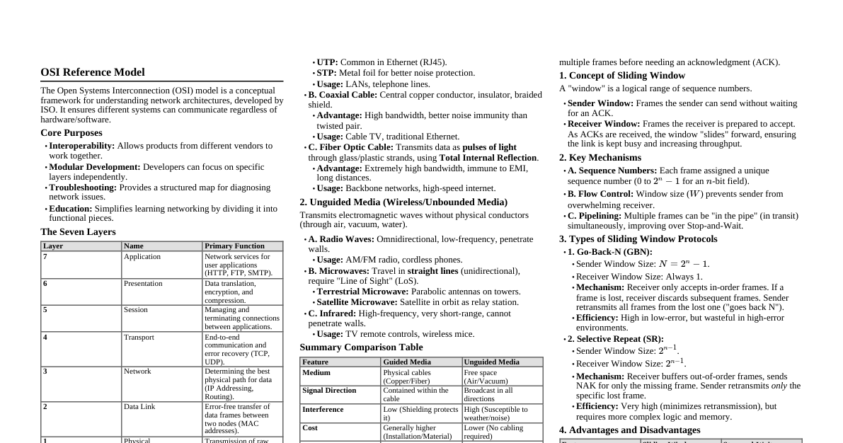
Overview of Computer Networks A network is a collection of interconnected devices and systems that are capable of sharing and exchanging data. Networks enable communication and collaboration among devices, facilitating the efficient transfer of information. Importance of Computer Networks Communication: Facilitates instant communication (emails, messaging, video conferencing). Resource Sharing: Enables sharing of files, printers, internet connections, reducing costs. Data Management & Storage: Centralized data storage, backup, security (e.g., cloud computing). Collaboration: Supports collaborative work environments for multiple users. Economic Efficiency: Reduces physical infrastructure needs, enables remote work, cost savings. Access to Information: Internet provides access to vast information, educational resources. Entertainment: Platforms for streaming, online gaming, social media. E-commerce: Revolutionized shopping and banking, global market access. Automation & Control: Used in industries for process automation, system monitoring. Security & Surveillance: Supports advanced security systems (cameras, alarms). Healthcare: Telemedicine, electronic health records, online information systems. Scalability & Flexibility: Allows businesses to scale operations easily without significant infrastructure investment. Historical Development of Networking Early Foundations: 1830s-1870s: Telegraph & Telephone: Laid groundwork for electronic communication. 1961-1964: Packet Switching: Leonard Kleinrock developed theory (data transmission in packets). The ARPANET Era: 1969: ARPANET: First operational packet-switching network (U.S. DoD). 1971: Email: Ray Tomlinson developed the first email system. Expansion & Standardization: 1970s: Development of Protocols: TCP/IP developed. 1983: TCP/IP Adoption: ARPANET officially adopted TCP/IP. Formation of the Internet: 1980s: Domain Name System (DNS): Introduced for navigation using domain names. 1989-1991: World Wide Web: Tim Berners-Lee invented WWW (first web browser/server). Commercialization & Globalization: 1990s: Internet Commercialization: Transitioned from academic to commercial. 1995: Public Internet Access: Commercial ISPs began offering public access. Mobile & Wireless Networking: 1990s-2000s: Mobile Networks: 2G, 3G, 4G enabled mobile Internet. 1997: Wi-Fi: IEEE 802.11 standard for wireless networking. The Modern Era: 2000s-Present: Broadband & Fiber Optics: Increased Internet speeds and capacity. 2010s: Cloud Computing: Scalable data storage/processing. 2020s: 5G & IoT: Faster speeds, lower latency for IoT, autonomous vehicles. Future Prospects: Quantum Networking: Research for secure communications, faster data transfer. Global Connectivity: Projects like Starlink for global Internet coverage. Layered Architecture in Computer Networks A model where a whole network process is divided into various smaller sub-tasks, with each layer performing dedicated tasks. Lower layers add services to higher layers. Modifications in one layer do not affect others. Features of Layered Architecture Modularity & Distinct Interfaces: Provides clear separation of concerns. Independence: Layers offer services without specifying implementation details. Segmentation: Breaks down large designs into smaller, manageable sub-tasks. Variety of Functions: Each network has different functions, layers, and content. Physical Route: Physical communication available under Layer 1. Modifiability: Implementation in one layer can be modified without affecting others. Elements of Layered Architecture Service: Set of functions provided by a lower layer to a higher layer. Protocol: Set of rules for data exchange and transmission within a layer. Interface: Channel for transmitting messages between layers. Need for Layered Architecture Divide and Conquer Approach: Reduces complexity by breaking down tasks. Easy to Modify: Independent layers allow changes without affecting others. Modularity: More modular, easier to understand. Easy to Test: Each layer can be analyzed and tested individually. Application of Layered Architecture Majorly used for communication in computer networks: OSI Model TCP/IP Model OSI Model Created in 1984 by ISO, a reference framework explaining data transmission between computers. It consists of seven layers. 7 Layers of the OSI Model (Top-Down Order) Application Layer (Layer 7): User interface, network services for applications. Presentation Layer (Layer 6): Data translation, encryption, compression. Session Layer (Layer 5): Establishes, manages, and terminates sessions between applications. Transport Layer (Layer 4): End-to-end communication, segmentation, flow/error control. Network Layer (Layer 3): Routing, logical addressing (IP addresses). Data Link Layer (Layer 2): Node-to-node data transfer, framing, physical addressing, error detection. Physical Layer (Layer 1): Physical connection, bit transmission, electrical/optical signals. Functions of Each OSI Layer Physical Layer (Layer 1) Responsibility: Actual physical connection, transmitting individual bits. Functions: Bit synchronization: Provides clock for sender/receiver synchronization. Bit rate control: Defines transmission rate (bits per second). Physical topologies: Specifies device arrangement (bus, star, mesh). Transmission mode: Defines data flow (simplex, half-duplex, full-duplex). Devices: Hub, Repeater, Modem, Cables. Data Link Layer (Layer 2) Responsibility: Node-to-node delivery, error-free data transfer over physical layer. Sublayers: Logical Link Control (LLC), Media Access Control (MAC). Functions: Framing: Divides data into meaningful frames with start/end patterns. Physical addressing: Adds MAC addresses to frame headers. Error control: Detects and retransmits damaged/lost frames. Flow Control: Coordinates data rate to prevent data corruption. Access control: MAC sub-layer determines device control over shared channel. Devices: Switch, Bridge. Note: Packet in DLL is called a Frame . Handled by NIC and device drivers. Network Layer (Layer 3) Responsibility: Data transmission from host to host across different networks, packet routing. Functions: Routing: Determines the best path from source to destination. Logical Addressing: Places sender/receiver IP addresses in header for unique identification. Devices: Routers, Switches. Note: Segment in Network Layer is called a Packet . Transport Layer (Layer 4) Responsibility: End-to-end delivery of complete message, acknowledgment, retransmission on error. Functions: Segmentation & Reassembly: Breaks messages into smaller segments at sender, reassembles at receiver. Service Point Addressing: Uses port addresses to deliver data to correct processes. Services: Connection-Oriented Service: Three phases (establishment, transfer, termination), reliable, secure (e.g., TCP). Connectionless Service: One phase (transfer), faster, no acknowledgment (e.g., UDP). Note: Data in Transport Layer is called Segments . Considered "Heart of the OSI model". Protocols: TCP, UDP, NetBIOS, PPTP. Session Layer (Layer 5) Responsibility: Establishes, maintains, and terminates connections; authentication, security. Functions: Session establishment, maintenance, & termination: Manages connection lifecycle. Synchronization: Adds checkpoints to re-synchronize data and prevent loss. Dialog Controller: Manages communication mode (half-duplex/full-duplex). Protocols: NetBIOS, PPTP. Presentation Layer (Layer 6) Responsibility: Data translation, encryption/decryption, compression for network transmission. Functions: Translation: Converts data format (e.g., ASCII to EBCDIC). Encryption/Decryption: Transforms data for security. Compression: Reduces data size for efficient transmission. Protocols: JPEG, MPEG, GIF. Application Layer (Layer 7) Responsibility: Provides network services to end-user applications, displays received information. Functions: Network Virtual Terminal (NVT): Allows remote login. File Transfer Access and Management (FTAM): Access, retrieve, manage files on remote hosts. Mail Services: Provides email services. Directory Services: Provides distributed database access for global information. Examples: Browsers, Skype, Email clients (Gmail, Outlook). Protocols: SMTP. Flow of Data in OSI Model (Example: Sending an Email) Application Layer (L7): User interacts with email app (e.g., Gmail) to compose email. Presentation Layer (L6): Email app prepares data: encrypts, compresses, formats. Session Layer (L5): Connection established between sender and receiver. Transport Layer (L4): Email data broken into segments, sequence numbers and error-checking added. Network Layer (L3): Packets addressed, best route determined for transfer. Data Link Layer (L2): Data encapsulated into frames, MAC address added, error detection performed. Physical Layer (L1): Frames transmitted as electrical/optical signals over network medium. At the receiver, the process reverses: L1 to L7, decrypting and reassembling the email. Advantages of OSI Model Divides network communication into 7 layers, making it easier to understand and troubleshoot. Standardizes network communications with fixed functions and protocols per layer. Easier to diagnose network problems. Allows for easier improvements and updates to individual layers. TCP/IP Model Developed by DoD in the 1960s, based on standard protocols. It's a concise version of the OSI model, containing four layers (sometimes five, including Physical). What Does TCP/IP Do? Transfers data reliably and accurately by dividing it into packets at the sender's end and recombining them at the receiver's end. Layers of TCP/IP Model (Common 5-Layer View) Application Layer Transport Layer (TCP/UDP) Network/Internet Layer (IP) Data Link Layer (MAC) Physical Layer TCP/IP Model vs. OSI Model (Layer Mapping) TCP/IP Layer OSI Layer(s) Protocols/Description Application Layer Application, Presentation, Session HTTP, HTTPS, FTP, SMTP, DNS, SNMP, TELNET, TFTP, RPC. Handles application-specific data and services. Transport Layer Transport TCP, UDP. Provides end-to-end communication, segmentation, flow/error control. Internet Layer Network IP, ICMP, IGMP, ARP, RARP. Handles logical addressing and routing. Data Link Layer Data Link Ethernet, PPP. Handles node-to-node data transfer, framing, MAC addressing. Physical Layer Physical Cables, Hubs, Repeaters. Handles physical transmission of bits. Difference between TCP/IP and OSI Model Feature TCP/IP Model OSI Model Reference TCP refers to Transmission Control Protocol. OSI refers to Open Systems Interconnection. Layer Consolidation Combines Session and Presentation into Application Layer. Has separate Session and Presentation layers. Approach Follows a connectionless, horizontal approach. Follows a vertical approach. Delivery Assurance Transport layer (TCP) provides assurance delivery. Transport layer provides assurance delivery. Protocol Replacement Protocols cannot be replaced easily. Protocols are better covered and easy to replace. Network Layer Services Network layer provides connectionless (IP) services. Network layer provides connectionless and connection-oriented services. Flexibility More flexible as all packets are treated as independent entities. Less flexible. Switching Techniques In large networks, switching techniques decide the best route for data transmission and connect systems for one-to-one communication. Classification of Switching Techniques Circuit Switching Message Switching Packet Switching Datagram Approach Virtual Circuit Approach Switched Virtual Circuit (SVC) Permanent Virtual Circuit (PVC) Circuit Switching Definition: Establishes a dedicated path between sender and receiver. Process: Connection remains until terminated. Similar to a telephone call. Phases: Circuit establishment Data transfer Circuit Disconnect Usage: Public telephone networks, voice transmission. Advantages: Dedicated communication channel. Fixed bandwidth. Disadvantages: Delay during connection establishment. More expensive (dedicated path). Inefficient (capacity wasted if no data transferred). Space Division Switches (for Circuit Switching) Concept: Single transmission path using physically separate crosspoints. Crossbar Switch: Metallic crosspoint or semiconductor gate that can be enabled/disabled. Has $n$ input lines and $n$ output lines, with $n^2$ crosspoints. Disadvantage: Number of crosspoints increases with stations, making it expensive for large switches. Multistage Switch: Splits crossbar switch into smaller units and interconnects them. Reduces number of crosspoints. Provides alternative paths if one fails. Message Switching Definition: Message transferred as a complete unit, routed through intermediate nodes where it's stored and forwarded. Process: No dedicated path. Dynamic routing based on message information. Each node stores the entire message before forwarding. Network Type: Known as store-and-forward network. Advantages: Shared data channels, improved bandwidth efficiency. Reduced traffic congestion (messages stored). Message priority can be used. Supports variable, unlimited message sizes. Disadvantages: Requires sufficient storage at switches. Long delays due to store-and-forward mechanism. Packet Switching Definition: Message divided into smaller pieces (packets), sent individually. Process: Packets given unique numbers for order. Each packet contains header info (source/dest address, sequence number). Packets travel shortest path, reassembled at receiver. Retransmission if missing/corrupted. Approaches to Packet Switching Datagram Packet Switching (Connectionless): Each packet (datagram) is an independent entity. Contains destination information for routing. Packets reassembled at receiver. Path is not fixed. Intermediate nodes make routing decisions. Virtual Circuit Switching (Connection-Oriented): Preplanned route established before messages sent. Call request/accept packets establish connection. Path is fixed for the duration of a logical connection. Differences between Datagram and Virtual Circuit Approach Feature Datagram Approach Virtual Circuit Approach Routing Decisions Node takes routing decisions to forward packets. Node does not take any routing decision (path fixed). Congestion Congestion cannot occur as packets travel in different directions. Congestion can occur if a node is busy. Flexibility More flexible as packets are independent. Not very flexible. Advantages of Packet Switching Cost-effective: Less secondary storage needed, so lower cost. Reliable: Packets can be rerouted if a node is busy. Efficient: No established path needed, multiple users share channel, efficient bandwidth use. Disadvantages of Packet Switching Not suitable for applications requiring low delay and high-quality services. Complex protocols, high implementation cost. Retransmission of lost packets if network is overloaded/corrupted. Potential loss of critical information if errors not recovered. Data Link Layer Services & Framing The Data Link Layer is the 2nd layer from the bottom (4th from top) in the OSI model. Its main responsibility is to transfer datagrams across an individual link. Key Characteristics Defines packet format for exchange, actions like error detection, retransmission, flow control, random access. Protocols include Ethernet, Token Ring, FDDI, PPP. Can handle different link layer protocols on different links within a path. Services Provided by Data Link Layer Framing & Link access: Encapsulates network frames into link layer frames. Defines frame structure and channel access protocol. Reliable Delivery: Transmits network layer datagrams without error, using retransmissions and acknowledgments. Flow Control: Prevents receiver buffer overflow by coordinating data rate. Error Detection: Detects errors introduced by signal attenuation/noise using error detection bits. Error Correction: Not only detects errors but also determines where they occurred. Half-Duplex & Full-Duplex: Manages simultaneous or one-way transmission. Framing Techniques Framing divides a stream of bits into discernible blocks (frames). Each frame has a header for error-checking and other information. Problems in Framing Detecting start of the frame: Stations look for a Special Frame Delimiter (SFD). How to detect a frame: Stations listen for SFD, alert on detection, check destination address. Detecting end of frame: Knowing when to stop reading the frame. Handling errors: Framing errors from noise/transmission errors; uses CRC for integrity. Framing overhead: Header/trailer control info reduces available bandwidth. Framing incompatibility: Different devices/protocols may use different framing methods. Framing synchronization: Stations must be synchronized for reliable communication. Framing efficiency: Minimize data overhead, maximize bandwidth. Types of Framing Fixed-size: Frame length acts as a delimiter. Drawback: Internal fragmentation if data size is less than frame size. Solution: Padding. Variable size: Requires explicit start/end frame delimiters. Length field: Indicates frame length (e.g., Ethernet 802.3). Problem: field can get corrupted. End Delimiter (ED): Pattern indicates end of frame (e.g., Token Ring). Problem: ED can appear in data. Character/Byte Stuffing: Inserts a byte (escape character) into data if ED pattern appears. Bit Stuffing: Inserts a bit to break ED pattern if it appears in data. Receiver removes the stuffed bit. Error Detection in Computer Networks Errors occur when digital signals are corrupted by noise during transmission, changing bits (0 to 1 or 1 to 0). Types of Errors Single-Bit Error: Only one bit in a data unit is altered. Multiple-Bit Error: More than one bit in a data unit is affected. (Relatively rare, but can occur in noisy environments). Burst Error: Several consecutive bits are flipped, causing a sequence of incorrect values. Error Detection Methods (using Redundancy Bits) Simple Parity Check: Adds an extra bit (parity bit) to make the total number of 1s in a block even (even parity). Disadvantage: Cannot detect an even number of bit errors. Two-dimensional Parity Check: Calculates parity bits for each row and each column. Both row and column parity bits are sent with data. Receiver compares calculated parities with received parities. Checksum: Divides data into segments, calculates sum using 1's complement arithmetic. Sender complements the sum to get the checksum and sends it with data. Receiver adds all segments (including checksum), complements the sum. If result is zero, data is accepted; otherwise, discarded. Cyclic Redundancy Check (CRC): Based on binary division. Appends redundant bits (CRC bits) to data unit. Resulting data unit is exactly divisible by a predetermined binary number (generator polynomial). Receiver divides incoming data unit by the same number. No remainder means data is correct. A remainder indicates data damage, so it's rejected. Advantages of Error Detection Increased Data Reliability: Ensures accurate data transmission. Improved Network Performance: Helps identify and isolate network issues. Enhanced Data Security: Helps ensure data integrity and detect tampering. Disadvantages of Error Detection Overhead: Requires additional resources and processing, increasing latency. False Positives: Can lead to unnecessary retransmission of data. Limited Error Correction: Only identifies errors; cannot correct them, requiring retransmission. Multiple Access Control (MAC) When multiple stations share a non-dedicated communication channel, MAC protocols are needed to manage access, decrease collisions, and avoid crosstalk. Classification of Multiple Access Protocols Random Access Protocols Controlled Access Protocols Channelization Protocols Random Access Protocols All stations have equal priority. No fixed time or sequence for sending data. ALOHA: Designed for wireless LANs, allows multiple stations to transmit simultaneously, leading to collisions. Pure Aloha: Station sends data, waits for acknowledgment. If no ack, waits a random back-off time (Tb) and resends. Slotted Aloha: Time is divided into slots; transmission allowed only at the beginning of slots. Reduces collision probability. Carrier Sense Multiple Access (CSMA): Stations sense the medium before transmitting to reduce collisions. If idle, transmit; if busy, wait. Still prone to collisions due to propagation delay. 1-persistent CSMA: Senses channel, if idle, sends data. If busy, continuously checks and sends immediately when idle. Non-Persistent CSMA: Senses channel, if idle, sends data. If busy, waits a random time before checking again. P-persistent CSMA: Senses channel, if idle, sends with probability $p$. If not sent ($1-p$), waits and checks again. Used in Wi-Fi. O-persistent CSMA: Nodes have predefined priority; transmission occurs in that order. CSMA with Collision Detection (CSMA/CD): Stations can terminate transmission if collision is detected. (More details: Efficiency of CSMA/CD). CSMA with Collision Avoidance (CSMA/CA): Avoids collisions by detecting acknowledgments. If only one signal (own) is received, successful. If two (own + collided), collision occurred. Used in wired networks where collision detection is difficult. Interframe Space (IFS): Station waits for medium to be idle + IFS duration before sending. Contention Window: Random number of slots chosen as wait time; doubles on medium busy; timer restarts when channel idle. Acknowledgment: Sender re-transmits if ack not received. Controlled Access Protocols Data is sent only by approved stations. Reservation: Stations reserve a time slot for transmission. Polling: A central device polls stations to grant transmission rights. Token Passing: A special token circulates among stations; only the station with the token can transmit. Channelization Protocols Shares available bandwidth in time, frequency, or code to allow multiple stations simultaneous access. Frequency Division Multiple Access (FDMA): Divides bandwidth into equal bands, each allocated to a station. Uses guard bands to prevent overlap. Time Division Multiple Access (TDMA): Divides time into slots, each allotted to a station. Requires synchronization bits and guard bands for propagation delay. Code Division Multiple Access (CDMA): One channel carries all transmissions simultaneously. Uses different "code languages" for stations. Orthogonal Frequency Division Multiple Access (OFDMA): Divides bandwidth into small subcarriers to increase overall performance. Used in 5G. Advantages: Increased efficiency, high data rates, good for multimedia traffic. Disadvantages: Complex to implement, high peak-to-power ratio.