Fluid Mechanics (Chemical Eng.)
Cheatsheet Content
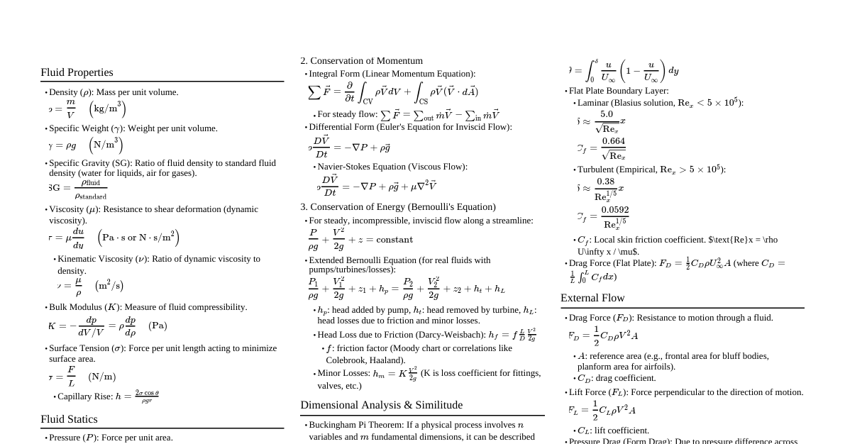
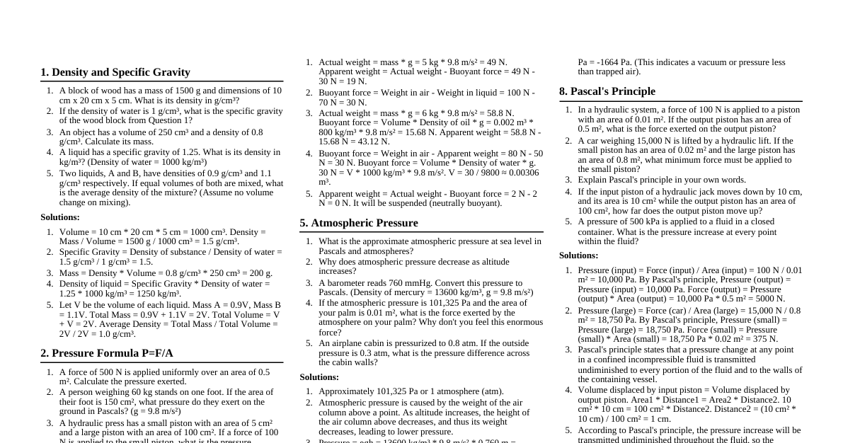
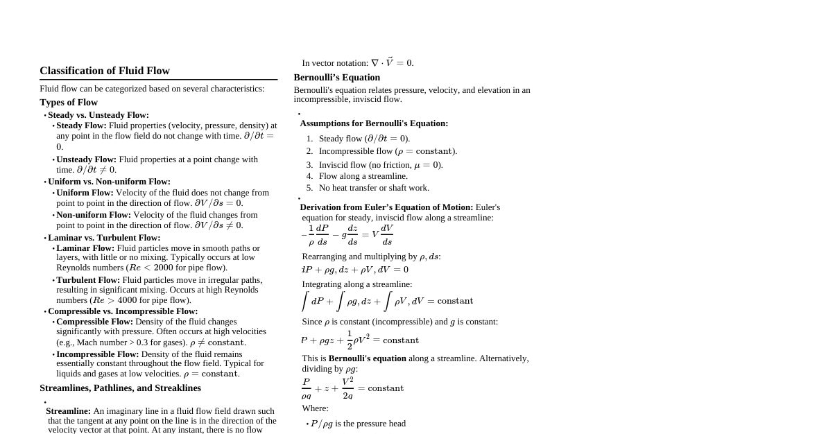
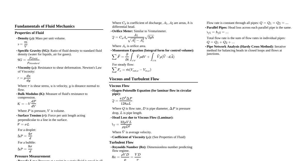
tags for improved readability"> tags for improved readability"> 1. Fluid Properties & Statics (Unit 1) 1.1 Fluid Properties Density ($\rho$): Mass per unit volume ($kg/m^3$). Formula: $\rho = m/V$ $m$: mass ($kg$), $V$: volume ($m^3$). Specific Volume ($v$): Volume per unit mass ($m^3/kg$). Formula: $v = V/m = 1/\rho$. Specific Weight ($\gamma$): Weight per unit volume ($N/m^3$). Formula: $\gamma = \rho g$. $g$: acceleration due to gravity ($9.81 \, m/s^2$). Specific Gravity (SG): Ratio of fluid density to standard fluid density (water at $4^\circ C$). Dimensionless. Formula: $SG = \rho_{fluid}/\rho_{water, 4^\circ C}$. Viscosity: Fluid's resistance to shear deformation. Dynamic Viscosity ($\mu$): Absolute viscosity ($Pa \cdot s$ or $kg/(m \cdot s)$). Kinematic Viscosity ($\nu$): Ratio of dynamic viscosity to density ($m^2/s$). $\nu = \mu/\rho$. Newton's Law of Viscosity: Relates shear stress to shear rate for Newtonian fluids. Formula: $\tau = \mu \frac{du}{dy}$. $\tau$: shear stress ($Pa$). $\frac{du}{dy}$: velocity gradient or shear rate ($s^{-1}$). Surface Tension ($\sigma$): Force per unit length at a liquid-gas interface ($N/m$). Capillary Rise: Rise/fall of liquid in a narrow tube. Formula: $h = \frac{2\sigma \cos\theta}{\rho g R}$. $h$: capillary rise (m). $\theta$: contact angle (wetting $\theta 90^\circ$). $R$: tube radius (m). 1.2 Fluid Statics & Pressure Measurement Pressure: Force exerted per unit area ($Pa$ or $N/m^2$). Absolute Pressure ($P_{abs}$): Relative to perfect vacuum. $P_{abs} = P_{gage} + P_{atm}$. Gage Pressure ($P_{gage}$): Relative to local atmospheric pressure. Hydrostatic Pressure: Pressure due to a fluid at rest. Formula: $P = \rho g h$. $h$: depth of fluid from free surface (m). Manometry: Using fluid columns to measure pressure differences. Manometer Equation: $P_{start} + \sum (\rho g h)_{down} - \sum (\rho g h)_{up} = P_{end}$. 1.3 Forces on Submerged Bodies Resultant Hydrostatic Force ($F_R$): Total force on a submerged plane surface. Formula: $F_R = P_c A = \rho g h_c A$ ($N$). $P_c$: pressure at the centroid ($Pa$). $A$: area of submerged surface ($m^2$). $h_c$: depth of the centroid from free surface (m). Center of Pressure ($y_p$): Point where $F_R$ acts. Formula: $y_p = y_c + \frac{I_{xx,c}}{y_c A}$ (m). $y_c$: distance to centroid from free surface along inclined plane (m). $I_{xx,c}$: moment of inertia about centroidal axis parallel to free surface ($m^4$). For a rectangular plate: $I_{xx,c} = \frac{bh^3}{12}$. Buoyancy (Archimedes' Principle): Upward force on an immersed object. Formula: $F_B = \rho_f g V_{submerged}$ ($N$). $\rho_f$: fluid density ($kg/m^3$). $V_{submerged}$: volume of fluid displaced ($m^3$). For floating objects, $F_B = W_{object}$. 2. Fluid Dynamics & Incompressible Flow (Unit 1) 2.1 Conservation Equations Equation of Continuity (Mass Conservation): For steady, 1D flow. General: $\dot{m} = \rho_1 A_1 V_1 = \rho_2 A_2 V_2$ ($kg/s$). Incompressible Flow: $A_1 V_1 = A_2 V_2 = Q$ ($m^3/s$). Equation of Momentum: Control Volume Form. Formula: $\sum F = \sum_{out} \dot{m} V - \sum_{in} \dot{m} V$ ($N$). Used for forces on pipe bends, impellers, etc. Bernoulli’s Equation (Energy Conservation): Ideal Fluid (Incompressible, Inviscid, Steady, along streamline): $\frac{P}{\rho g} + \frac{V^2}{2g} + z = constant$ (m). Real Fluid (Extended Bernoulli, between two points): Accounts for pumps, turbines, and losses. $\frac{P_1}{\rho g} + \frac{V_1^2}{2g} + z_1 + h_p = \frac{P_2}{\rho g} + \frac{V_2^2}{2g} + z_2 + h_t + h_L$ (m). $h_p$: head added by pump (m). $h_p = W_p/(\dot{m}g)$. $h_t$: head extracted by turbine (m). $h_t = W_t/(\dot{m}g)$. $h_L$: total head loss (m). Navier-Stokes Equation: Fundamental momentum equation for Newtonian fluids. $\rho \left( \frac{\partial \mathbf{V}}{\partial t} + (\mathbf{V} \cdot \nabla) \mathbf{V} \right) = -\nabla P + \mu \nabla^2 \mathbf{V} + \rho \mathbf{g}$ Vector equation, solutions give velocity and pressure fields. 2.2 Types of Fluids & Flow Regimes Newtonian Fluids: $\tau = \mu \frac{du}{dy}$ ($\mu$ is constant). E.g., water, air. Non-Newtonian Fluids: Viscosity depends on shear rate. Pseudoplastic (Shear Thinning): $n Formula: $\tau = K |\frac{du}{dy}|^{n-1} \frac{du}{dy}$. E.g., paint. Dilatant (Shear Thickening): $n>1$ in Power Law Model. E.g., cornstarch solution. Bingham Plastic: Requires yield stress $\tau_y$ to flow. Formula: $\tau = \tau_y + \mu_p \frac{du}{dy}$ (for $\tau > \tau_y$). E.g., toothpaste. Laminar Flow: Smooth, orderly fluid motion. Low $Re$. Turbulent Flow: Chaotic, irregular fluid motion. High $Re$. Reynolds Number ($Re$): Dimensionless flow regime predictor. Formula: $Re = \frac{\rho V D}{\mu} = \frac{VD}{\nu}$. $D$: characteristic length (e.g., pipe diameter). Pipe flow: $Re 4000$ (Turbulent). 3. Incompressible Flow in Pipes & Fluidization (Unit 1) 3.1 Flow in Pipes Velocity Distribution in Pipes: Laminar: Parabolic profile, $u(r) = u_{max} (1 - r^2/R^2)$, $u_{max} = 2 V_{avg}$. Turbulent: Flatter profile centrally, steeper near wall. Frictional Losses in Pipes: Laminar Flow (Hagen-Poiseuille): Pressure Drop: $\Delta P = \frac{32 \mu L V_{avg}}{D^2}$ ($Pa$). Volumetric Flow Rate: $Q = \frac{\pi D^4 \Delta P}{128 \mu L}$ ($m^3/s$). Friction Factor: $f = \frac{64}{Re}$. Turbulent Flow (Darcy-Weisbach Equation): Head Loss: $h_L = f \frac{L}{D} \frac{V^2}{2g}$ (m). $f$: Darcy friction factor (dimensionless). $L$: pipe length (m), $D$: pipe inner diameter (m). $V$: average flow velocity ($m/s$). Friction Factor ($f$) for Turbulent Flow: Smooth Pipes (Blasius, $Re $f \approx \frac{0.316}{Re^{0.25}}$. Rough Pipes (Colebrook-White, implicit): $\frac{1}{\sqrt{f}} = -2.0 \log_{10} \left( \frac{\epsilon/D}{3.7} + \frac{2.51}{Re\sqrt{f}} \right)$. Moody Chart: Graphical tool for $f$ based on $Re$ and relative roughness ($\epsilon/D$, $\epsilon$ is absolute roughness). Frictional Losses in Fittings (Minor Losses): Formula: $h_{L,minor} = K \frac{V^2}{2g}$ (m). $K$: loss coefficient (dimensionless, specific to fitting). Pressure Drop Calculations: Sum of major (friction) and minor losses. $\Delta P_{total} = \Delta P_{friction} + \Delta P_{minor} + \Delta P_{elevation} + \Delta P_{acceleration}$. Economic Pipe Diameter: Balances capital cost (pipe size) and operating cost (pumping power). 3.2 Fluidization Concept Fluidization: Granular material behaves like a fluid when a fluid passes through it. Minimum Fluidization Velocity ($U_{mf}$): Velocity at which a packed bed begins to fluidize. At $U_{mf}$, $\Delta P_{bed} = (1-\epsilon_{mf}) (\rho_s - \rho_f) g L_{bed}$. Ergun Equation (Pressure Drop in Packed Beds): $\frac{\Delta P}{L} = 150 \frac{\mu V_s (1-\epsilon)^2}{(\phi_s d_p)^2 \epsilon^3} + 1.75 \frac{\rho V_s^2 (1-\epsilon)}{(\phi_s d_p) \epsilon^3}$ ($Pa/m$). $V_s$: superficial velocity ($m/s$). $\epsilon$: void fraction (dimensionless). $\phi_s$: sphericity of particles (dimensionless). $d_p$: particle diameter (m). 4. Measurement & Control of Flowing Fluids (Unit 2) 4.1 Measurement of Flowing Fluids Variable Head Meters (Venturi, Orifice, Nozzle): Measure flow by creating a pressure drop. Formula: $Q = C_d A_o \sqrt{\frac{2(P_1-P_2)}{\rho(1-\beta^4)}}$ ($m^3/s$). $C_d$: discharge coefficient (dimensionless). $A_o$: orifice/throat area ($m^2$). $\beta$: ratio of orifice/throat diameter to pipe diameter ($D_o/D_1$). Variable Area Meters (Rotameters): Float position indicates flow rate in a tapered tube. Pitot Tube: Measures local point velocity. Formula: $V = \sqrt{\frac{2(P_{stag} - P_{static})}{\rho}}$ ($m/s$). $P_{stag}$: stagnation pressure ($Pa$). $P_{static}$: static pressure ($Pa$). 4.2 Fluid Moving Machineries Pumps: Add energy to liquids. Fluid Power ($W_f$): $W_f = \dot{m} g h_p = \rho Q g h_p$ (W). Brake Power ($W_b$): $W_b = W_f / \eta_{pump}$ (W). Types: Centrifugal, Positive displacement. Blowers & Fans: Move gases at low to moderate pressure rises. Compressors: Significantly increase gas pressure. Turbines: Extract energy from fluid flow. Turbine Power: $W_t = \eta_{turbine} \dot{m} g h_t$ (W). Types: Impulse, Reaction. 4.3 Valves: Application and Selection Purpose: Control fluid flow (isolation, regulation, backflow prevention, pressure relief). Selection Factors: Function, fluid properties (corrosive, viscous), pressure, temperature, flow rate, material compatibility, cost. Significance: Crucial for safety (emergency shutdown), process control (maintaining parameters), and operational flexibility. Common Types: Gate, Globe, Ball, Plug, Butterfly, Check. 5. Boundary Layer Theory & Flow Past Immersed Bodies (Unit 3) 5.1 Boundary Layer Theory Boundary Layer: Thin fluid layer near a solid surface where viscous effects are significant. Velocity changes from zero (at wall) to free-stream. Boundary Layer Thickness ($\delta$): Distance from surface where velocity $\approx 99\%$ of free-stream. Laminar Flat Plate: $\delta \approx 5 \sqrt{\frac{\nu x}{U_\infty}}$ (m). Turbulent Flat Plate: $\delta \approx 0.37 x Re_x^{-1/5}$ (m). $x$: distance from leading edge (m), $U_\infty$: free-stream velocity ($m/s$). Laminar Sublayer: Innermost part of turbulent boundary layer, where viscous effects dominate. Turbulence: Chaotic fluid motion, enhancing mixing and transport. Reynolds Stress: Apparent stresses in turbulent flow due to fluctuating velocities (e.g., $-\rho \overline{u'v'}$). 5.2 Flow Past Immersed Bodies Drag Force ($F_D$): Resistance force opposing motion. Formula: $F_D = C_D \frac{1}{2} \rho U_\infty^2 A$ ($N$). $C_D$: drag coefficient (dimensionless). $A$: reference area ($m^2$). Components: Form Drag (pressure differences) and Skin Friction Drag (viscous shear). Lift Force ($F_L$): Force perpendicular to flow direction. Formula: $F_L = C_L \frac{1}{2} \rho U_\infty^2 A$ ($N$). $C_L$: lift coefficient (dimensionless). Motion of Solids Through a Fluid: Terminal Velocity: Constant velocity when drag equals net gravitational force. Stokes' Law (Creeping Flow, $Re_p $F_D = 3 \pi \mu d_p V$. Settling Velocity: Terminal velocity of a particle falling in a fluid. 6. Flow of Compressible Fluid (Unit 4) 6.1 Basic Equations & Isentropic Flow Compressible Flow: Density changes significantly (e.g., at high velocities). Speed of Sound ($c$): Velocity of pressure waves. For ideal gas: $c = \sqrt{kRT}$. $k$: ratio of specific heats ($c_p/c_v$). $R$: specific gas constant. $T$: absolute temperature (K). Mach Number ($Ma$): Ratio of flow velocity to speed of sound. Formula: $Ma = V/c$. $Ma 1$: Supersonic. Isentropic Flow Relations (Ideal Gas, constant $k$): For reversible, adiabatic flow. Relate stagnation (total) properties (subscript '0') to static properties. $\frac{T_0}{T} = 1 + \frac{k-1}{2} Ma^2$. $\frac{P_0}{P} = \left(1 + \frac{k-1}{2} Ma^2\right)^{k/(k-1)}$. $\frac{\rho_0}{\rho} = \left(1 + \frac{k-1}{2} Ma^2\right)^{1/(k-1)}$. Choked Flow: Maximum mass flow rate achieved when $Ma=1$ at the narrowest point (throat). 6.2 Flow Through Ducts & Nozzles Convergent-Divergent Nozzles (Laval Nozzle): Accelerates flow to supersonic speeds. Flow reaches $Ma=1$ at the throat. Supersonic acceleration occurs in the diverging section. Compressible Flow Measurement (Venturi/Orifice): Requires expansion factor ($Y$) for density changes. Formula: $Q_{actual} = Y Q_{incompressible}$. 6.3 Fanno Flow Fanno Flow: Adiabatic flow in a constant-area duct with friction. Entropy increases due to friction. Flow always tends towards $Ma=1$ (choking). Subsonic flow: $Ma$ increases towards 1. Supersonic flow: $Ma$ decreases towards 1. Fanno Line: Represents possible states on an $h-s$ diagram, with $Ma=1$ at max entropy. Maximum Duct Length: Length at which $Ma=1$ is reached for given inlet conditions.