Communication Systems Essentials
Cheatsheet Content
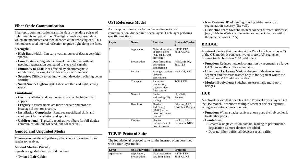
Amplitude Modulation (AM) Definition: In AM, the amplitude of the high-frequency carrier wave is varied in proportion to the instantaneous amplitude of the modulating (message) signal, while its frequency and phase remain constant. Equation: $s(t) = [A_c + k_a m(t)] \cos(2\pi f_c t)$ $A_c$: Carrier amplitude $k_a$: Amplitude sensitivity $m(t)$: Message signal $f_c$: Carrier frequency Need for Modulation: Antenna Size: For efficient radiation, antenna length must be comparable to $\lambda/4$. For low-frequency audio signals (e.g., 10 kHz), this would require impractically large antennas. Modulation shifts the signal to higher frequencies, reducing antenna size. Multiplexing: Allows multiple signals to share the same channel without interference by assigning each to a different carrier frequency. Increased Range: High-frequency signals can travel longer distances. Reduced Noise: Modulation can improve signal-to-noise ratio in some schemes. Modulation Index ($m_a$): $m_a = \frac{k_a A_m}{A_c}$, where $A_m$ is the peak amplitude of $m(t)$. Guided and Unguided Media Guided Media (Wired): Signals are confined to a physical path. They offer higher bandwidth, less interference, and secure transmission. Twisted Pair Cable: Two insulated copper wires twisted together to reduce electromagnetic interference. UTP (Unshielded Twisted Pair): Common for Ethernet. STP (Shielded Twisted Pair): Extra shielding for better noise immunity. Coaxial Cable: Central conductor surrounded by an insulator, a braided shield, and an outer jacket. Used for cable TV and older Ethernet. Fiber Optic Cable: Transmits data as light pulses through glass or plastic fibers. Single-mode: For long distances. Multi-mode: For shorter distances. Unguided Media (Wireless): Signals propagate through space without a physical conductor. Offer mobility but are prone to interference and have lower security. Radio Waves: Omnidirectional, used for broadcasting. Frequencies from 3 kHz to 300 GHz. Microwaves: Unidirectional, line-of-sight propagation. Used for point-to-point communication (e.g., satellite, cellular networks). Frequencies from 1 GHz to 300 GHz. Infrared Waves: Short-range, line-of-sight, cannot penetrate walls. Used for remote controls, short-range device communication. Frequencies from 300 GHz to 400 THz. Communication System Block Diagram Input Transducer Transmitter Communication Channel (Noise Source) Receiver Output Transducer Components: Input Transducer: Converts non-electrical message (e.g., sound, image) into an electrical signal. Transmitter: Processes the electrical signal for efficient transmission (e.g., modulation, amplification). Communication Channel: The medium through which the signal travels (e.g., cable, air). Noise is often added here. Receiver: Extracts the original message signal from the received signal (e.g., demodulation, amplification, filtering). Output Transducer: Converts the electrical signal back into its original form (e.g., sound, image). Relation between FM and PM Both Frequency Modulation (FM) and Phase Modulation (PM) are forms of Angle Modulation, where the angle of the carrier wave is varied according to the message signal. FM: The instantaneous frequency of the carrier is varied linearly with the message signal $m(t)$. $\phi_{FM}(t) = 2\pi f_c t + 2\pi k_f \int m(t) dt$ $s_{FM}(t) = A_c \cos(2\pi f_c t + 2\pi k_f \int m(t) dt)$ PM: The instantaneous phase of the carrier is varied linearly with the message signal $m(t)$. $\phi_{PM}(t) = 2\pi f_c t + k_p m(t)$ $s_{PM}(t) = A_c \cos(2\pi f_c t + k_p m(t))$ Relationship: If we integrate the message signal $m(t)$ before applying it to an FM modulator, the output will be a PM signal. If $m'(t) = \int m(t) dt$, then an FM signal with $m'(t)$ as input is $A_c \cos(2\pi f_c t + 2\pi k_f \int m'(t) dt) = A_c \cos(2\pi f_c t + 2\pi k_f \int (\int m(t) dt) dt)$. This is not a PM signal. Correct: If $m'(t) = \int m(t) dt$, then a PM signal with $m'(t)$ as input is $A_c \cos(2\pi f_c t + k_p m'(t)) = A_c \cos(2\pi f_c t + k_p \int m(t) dt)$. This is an FM signal. Conversely, if we differentiate the message signal $m(t)$ before applying it to a PM modulator, the output will be an FM signal. If $m'(t) = \frac{d}{dt} m(t)$, then an FM signal with $m'(t)$ as input is $A_c \cos(2\pi f_c t + 2\pi k_f \int m'(t) dt) = A_c \cos(2\pi f_c t + 2\pi k_f m(t))$. This is a PM signal. In essence, FM is phase modulation by the integral of the message signal, and PM is frequency modulation by the derivative of the message signal. Natural and Flat-Top Sampling Sampling is the process of converting a continuous-time analog signal into a discrete-time signal by taking samples at regular intervals. Natural Sampling: The amplitude of the pulses in the sampled signal follows the instantaneous amplitude of the message signal. The top of the sampled pulse retains the shape of the analog signal. It's simpler to implement but suffers from aperture effect distortion during reconstruction. Flat-Top Sampling: The amplitude of each sampled pulse is held constant at the instantaneous amplitude of the message signal at the sampling instant. The top of the pulse is flat. This is preferred for Pulse Amplitude Modulation (PAM) and Analog-to-Digital Conversion (ADC) because it's easier to generate and process. It also suffers from aperture effect, but it can be compensated. Equalization Process Equalization is a technique used in communication systems to compensate for frequency-dependent attenuation and phase distortion (inter-symbol interference, ISI) introduced by the communication channel. The goal is to restore the signal to its original form or as close as possible. Purpose: To minimize ISI and improve the signal-to-noise ratio (SNR) at the receiver. How it works: An equalizer is typically a filter (linear or non-linear, adaptive or fixed) that attempts to create an inverse response to the channel's distortion. Types: Linear Equalizers: Use linear filters (e.g., FIR, IIR). Decision Feedback Equalizers (DFE): Use previous decisions to cancel ISI on current symbols. Adaptive Equalizers: Adjust their filter coefficients dynamically based on the received signal characteristics, often using algorithms like Least Mean Squares (LMS). ASK, FSK, PSK These are digital modulation techniques where a digital bit stream modifies a carrier wave. Amplitude Shift Keying (ASK): The amplitude of the carrier wave is varied in accordance with the digital data, while its frequency and phase remain constant. Binary ASK (BASk): Two distinct amplitude levels (e.g., carrier ON for '1', carrier OFF for '0'). Equation: $s(t) = A_c \cdot b(t) \cos(2\pi f_c t)$, where $b(t)$ is the binary data (e.g., 1 or 0). Frequency Shift Keying (FSK): The frequency of the carrier wave is varied in accordance with the digital data, while its amplitude and phase remain constant. Binary FSK (BFSK): Two distinct frequencies represent '0' and '1'. Equation: $s(t) = A_c \cos(2\pi (f_c + \Delta f \cdot b(t)) t)$, where $b(t)$ is $\pm 1$ for '1' or '0'. Phase Shift Keying (PSK): The phase of the carrier wave is varied in accordance with the digital data, while its amplitude and frequency remain constant. Binary PSK (BPSK): Two phases (e.g., $0^\circ$ for '0', $180^\circ$ for '1'). Equation: $s(t) = A_c \cos(2\pi f_c t + \phi(t))$, where $\phi(t)$ is $0$ or $\pi$ depending on the data bit. Quadrature PSK (QPSK): Uses four phase shifts ($0^\circ, 90^\circ, 180^\circ, 270^\circ$) to encode two bits per symbol. Why ASK is called 'OOK'? ASK is often called On-Off Keying (OOK) , especially in its binary form. This is because for a binary '1', the carrier is "on" (transmitted with a certain amplitude), and for a binary '0', the carrier is "off" (no carrier is transmitted, or amplitude is zero). This on/off switching directly corresponds to the presence or absence of the carrier signal. OSI Reference Model The Open Systems Interconnection (OSI) model is a conceptual framework that standardizes the functions of a communication system into seven distinct layers. Each layer performs specific functions and communicates with the layers directly above and below it. Physical Layer (Layer 1): Deals with the physical transmission of raw bit streams over the physical medium. (e.g., cables, connectors, voltage levels, data rates). Data Link Layer (Layer 2): Provides reliable data transfer across a physical link. Handles error detection/correction, flow control, and defines physical addressing (MAC addresses). (e.g., Ethernet, PPP). Network Layer (Layer 3): Responsible for logical addressing (IP addresses) and routing of packets across multiple networks. (e.g., IP, ICMP). Transport Layer (Layer 4): Provides end-to-end communication, reliability, flow control, and segmentation/reassembly of data. (e.g., TCP, UDP). Session Layer (Layer 5): Manages communication sessions between applications, including establishment, management, and termination. (e.g., NetBIOS, RPC). Presentation Layer (Layer 6): Handles data format translation, encryption/decryption, and compression to ensure data is presented in a format understandable by the application layer. (e.g., JPEG, MPEG, ASCII). Application Layer (Layer 7): Provides network services directly to end-user applications. (e.g., HTTP, FTP, SMTP, DNS). TCP/IP Protocol Suite The Transmission Control Protocol/Internet Protocol (TCP/IP) suite is a set of communication protocols used for the Internet and similar computer networks. It's a pragmatic, widely implemented model, often described with four or five layers, loosely mapping to the OSI model. Layers (Commonly 4-Layer Model): Application Layer: Combines OSI Layers 5, 6, 7. Provides application-specific services. (e.g., HTTP, FTP, SMTP, DNS). Transport Layer: Maps to OSI Layer 4. Provides end-to-end communication. (e.g., TCP for reliable, connection-oriented; UDP for unreliable, connectionless). Internet Layer (Network Layer): Maps to OSI Layer 3. Handles logical addressing and routing of packets. (e.g., IP, ICMP, ARP). Network Access Layer (Link Layer/Physical Layer): Combines OSI Layers 1, 2. Deals with physical transmission and local network addressing. (e.g., Ethernet, Wi-Fi, PPP). Key Differences from OSI: TCP/IP is a protocol suite, not just a model. It's more flexible and less rigid in its layer definitions. It emerged from practical implementation rather than theoretical design. Fiber Optic Communication Fiber optic communication is a method of transmitting information from one place to another by sending pulses of light through an optical fiber. The light forms an electromagnetic carrier wave that is modulated to carry information. Principle: Based on Total Internal Reflection (TIR) . When light traveling in a denser medium (core) strikes the boundary with a less dense medium (cladding) at an angle greater than the critical angle, it is reflected back into the denser medium. This allows light to travel long distances inside the fiber with minimal loss. Components: Transmitter: Converts electrical signals into optical signals (e.g., LED, Laser Diode). Optical Fiber: The transmission medium (core, cladding, buffer coating). Receiver: Converts optical signals back into electrical signals (e.g., Photodiode, Avalanche Photodiode). Strength and Limitation of Fiber Optic Communication Strengths: High Bandwidth: Can carry vast amounts of data due to high carrier frequency (light). Low Loss: Signal attenuation is much lower than electrical cables, allowing longer transmission distances without repeaters. Immunity to EMI/RFI: Not affected by electromagnetic interference or radio frequency interference. Security: Difficult to tap without detection, offering higher security. Small Size & Lightweight: Thinner and lighter than copper cables, saving space. No Spark Hazard: No electrical current, safe in flammable environments. Limitations: Cost: Installation and component costs (transceivers) can be higher than copper for short distances. Fragility: Glass fibers are more fragile than copper and require careful handling. Installation Difficulty: Splicing and connecting fibers require specialized tools and expertise. Power Delivery: Cannot carry electrical power to remote devices. Limited Bending Radius: Can be damaged if bent too sharply. Unidirectional: Typically, one fiber transmits in one direction, requiring two fibers for full-duplex communication. Snell's Law Snell's Law describes the relationship between the angles of incidence and refraction for a light ray or other wave passing through a boundary between two different isotropic media, such as water and air, or core and cladding in optical fiber. Formula: $n_1 \sin\theta_1 = n_2 \sin\theta_2$ $n_1$: Refractive index of the first medium. $\theta_1$: Angle of incidence. $n_2$: Refractive index of the second medium. $\theta_2$: Angle of refraction. When light passes from a less dense medium ($n_1$) to a denser medium ($n_2$), it bends towards the normal ($\theta_2 \theta_1$). Reflection and Refraction Reflection: The phenomenon where a wave (e.g., light, sound) bounces off a surface when it encounters a boundary between two different media. The angle of incidence equals the angle of reflection. This is the principle behind mirrors. Refraction: The bending of a wave as it passes from one medium to another, caused by a change in its speed. The amount of bending is governed by Snell's Law and the refractive indices of the two media. This is why a spoon in water appears bent. Baud Rate and Bit Rate Baud Rate (Symbol Rate): The number of symbol changes, waveform changes, or signaling events across the transmission medium per second. A "symbol" can represent one or more bits. It is measured in bauds (symbols/second). Example: In BPSK, 1 symbol = 1 bit, so baud rate = bit rate. In QPSK, 1 symbol = 2 bits, so baud rate = bit rate / 2. Bit Rate: The number of bits transmitted per second. It is measured in bits per second (bps). Relationship: Bit Rate = Baud Rate $\times$ Number of bits per symbol. Network Topologies Network topology refers to the arrangement of the various elements (links, nodes, etc.) of a computer network. Star Topology: All devices are connected to a central hub, switch, or server. Advantages: Easy to install and manage, fault isolation (failure of one node doesn't affect others), easy to add/remove devices. Disadvantages: Single point of failure (central device failure brings down the entire network), requires more cable than bus. Ring Topology: Devices are connected in a closed loop, with each device connected to exactly two others. Data flows in one direction (unidirectional) or both (bidirectional). Advantages: Can handle high volume of traffic, no collision, equal access for all nodes. Disadvantages: Failure of one link or device can break the entire ring, difficult to add/remove devices, troubleshooting can be complex. Mesh Topology: Every device is connected to every other device in the network. Advantages: Highly fault-tolerant (many redundant paths), robust, high traffic capacity. Disadvantages: Extremely complex and expensive to implement (many connections), difficult to install. Partial Mesh: Some devices are connected to all others, while others are only connected to a subset. Hybrid Topology: A combination of two or more different topologies. Advantages: Inherits strengths of combined topologies, flexible, scalable. Disadvantages: Complex design and management, potentially expensive. Example: A star network connected to a bus network. Modem and Repeater Modem (Modulator-Demodulator): Function: Converts digital signals from a computer into analog signals suitable for transmission over analog lines (like telephone lines) and vice-versa. Modulation: Digital to Analog (at sender). Demodulation: Analog to Digital (at receiver). Use: Connects a local network (LAN) or a single computer to a wider area network (WAN) or the Internet. Repeater: Function: A network device that regenerates and retransmits signals to extend the reach of a network. It operates at the Physical Layer (OSI Layer 1). How it works: Receives a signal, cleans it (removes noise), amplifies it, and retransmits it to its original strength. Use: Overcomes cable length limitations, extends network segments. What is a Router? A router is a network device that forwards data packets between computer networks. It performs the "traffic directing" functions on the Internet. It operates at the Network Layer (OSI Layer 3). Function: Determines the best path for data packets to travel from source to destination across different networks. How it works: Uses IP addresses to make routing decisions, maintains routing tables, and connects different network segments (LAN to LAN, LAN to WAN). Key Features: Connects dissimilar networks (e.g., Ethernet to Wi-Fi). Provides network security (firewall capabilities). Enables communication between different subnets. LED, Wi-MAX, Bluetooth Architecture, Hub and Bridge LED (Light Emitting Diode): A semiconductor light source that emits light when current flows through it. Electrons in the semiconductor recombine with electron holes, releasing energy in the form of photons. In Communication: Used as light sources in short-distance fiber optic communication systems due to their low cost, reliability, and ease of modulation, though less powerful and slower than laser diodes. Wi-MAX (Worldwide Interoperability for Microwave Access): A wireless broadband communication standard (IEEE 802.16) designed to provide high-speed internet access over large areas (up to several kilometers). Features: Provides an alternative to wired broadband (DSL, cable), supports both fixed and mobile access. Architecture: Consists of a WiMAX base station (similar to a cellular tower) and subscriber stations (user devices). Bluetooth Architecture: A short-range wireless technology standard (IEEE 802.15.1) for exchanging data between fixed and mobile devices over short distances. Piconet: A small, ad-hoc network formed by 2 to 8 Bluetooth devices. One device is the "master" (controls communication), and up to 7 others are "slaves". Communication is typically one-to-many. Scatternet: Multiple interconnected piconets, where a device can be a master in one piconet and a slave in another. Hub: A basic network device that connects multiple computers or other network devices together. It operates at the Physical Layer (OSI Layer 1). Function: When a packet arrives at one port, it is copied to all other ports. This creates a single collision domain. Disadvantages: Low efficiency, high collision rate, broadcasts all traffic, no intelligence. Largely replaced by switches. Bridge: A network device that connects two or more LAN segments, operating at the Data Link Layer (OSI Layer 2). Function: Forwards or filters data frames based on MAC addresses. It learns MAC addresses and builds a forwarding table to send frames only to the segment where the destination device resides. Advantages: Reduces network traffic by creating separate collision domains, improves performance over hubs. Block Diagram of PCM and Digital Communication Pulse Code Modulation (PCM) Block Diagram Analog Input Sampler Quantizer Encoder PCM Signal Decoder Reconstruction Filter Analog Output Working: Sampling: Converts continuous analog signal into discrete-time samples. Quantization: Approximates each sample's amplitude to the nearest of a finite set of discrete levels. Encoding: Converts each quantized sample into a binary code (digital representation). Decoding: Converts the received binary code back into quantized samples. Reconstruction Filter (Low Pass Filter): Smooths the quantized samples to reconstruct an approximation of the original analog signal. Digital Communication System Block Diagram Source (Analog/Digital) Source Encoder Channel Encoder Digital Modulator Channel Noise Digital Demodulator Destination (User) Working: Source: Generates the message (analog or digital). Source Encoder: Converts analog to digital (if needed, like PCM) and removes redundancy for efficient representation. Channel Encoder: Adds redundant bits for error detection and correction. Digital Modulator: Converts digital bit stream into an analog waveform suitable for transmission over the channel (e.g., ASK, FSK, PSK). Channel: Transmits the modulated signal; introduces noise and distortion. Digital Demodulator: Converts the received analog waveform back into a digital bit stream. Channel Decoder: Detects and corrects errors introduced by the channel. Source Decoder: Reconstructs the original message signal. Destination: Receives the reconstructed message. Nyquist Sampling Theorem The Nyquist-Shannon sampling theorem states that to perfectly reconstruct a continuous-time analog signal from its samples, the sampling rate ($f_s$) must be at least twice the maximum frequency component ($f_{max}$) of the signal being sampled. Condition: $f_s \ge 2 f_{max}$ $f_s$: Sampling frequency (samples per second). $f_{max}$: Highest frequency component present in the analog signal. The minimum sampling rate, $2 f_{max}$, is known as the Nyquist Rate . Consequence of Undersampling (Aliasing): If $f_s Practical Considerations: In practice, a sampling rate slightly higher than the Nyquist rate is often used, and a low-pass anti-aliasing filter is applied before sampling to ensure that no frequencies above $f_s/2$ enter the sampler.