Diffraction, Interference & Polarization
Cheatsheet Content
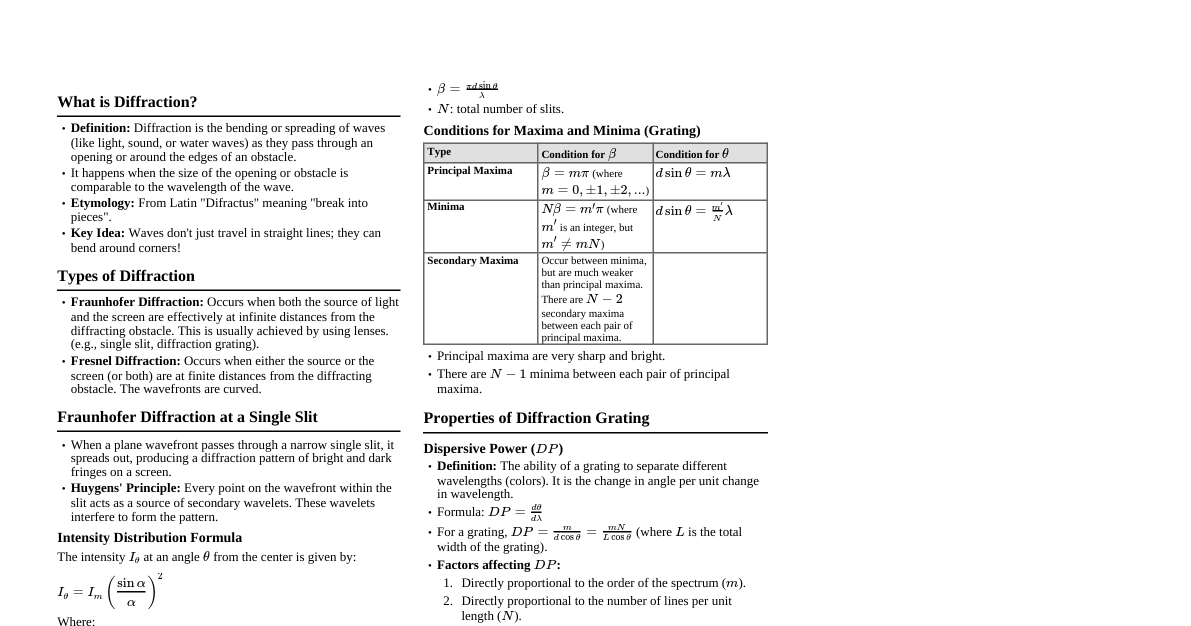
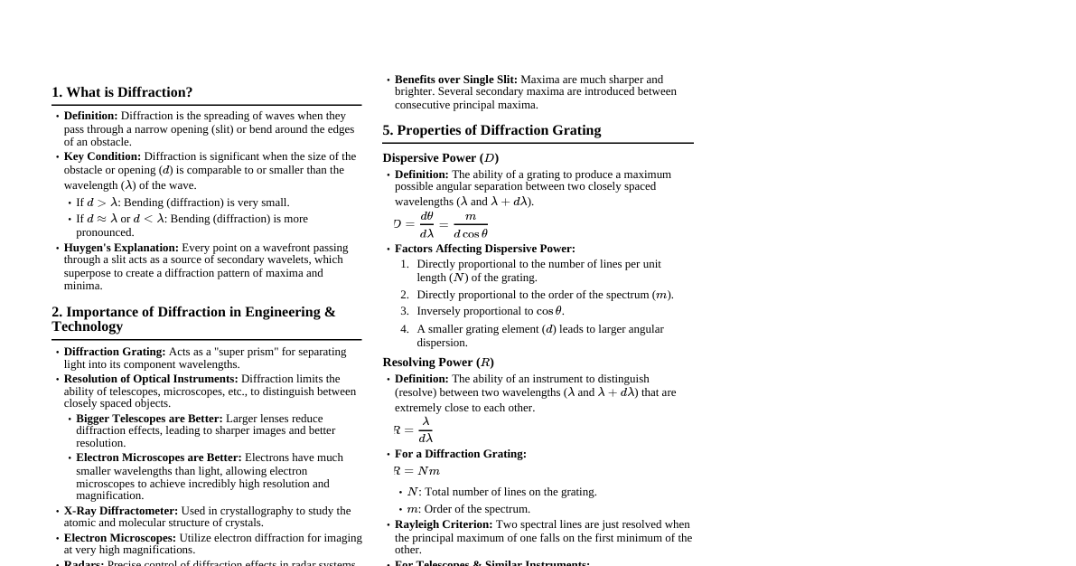
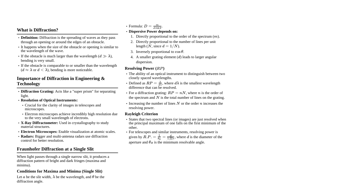
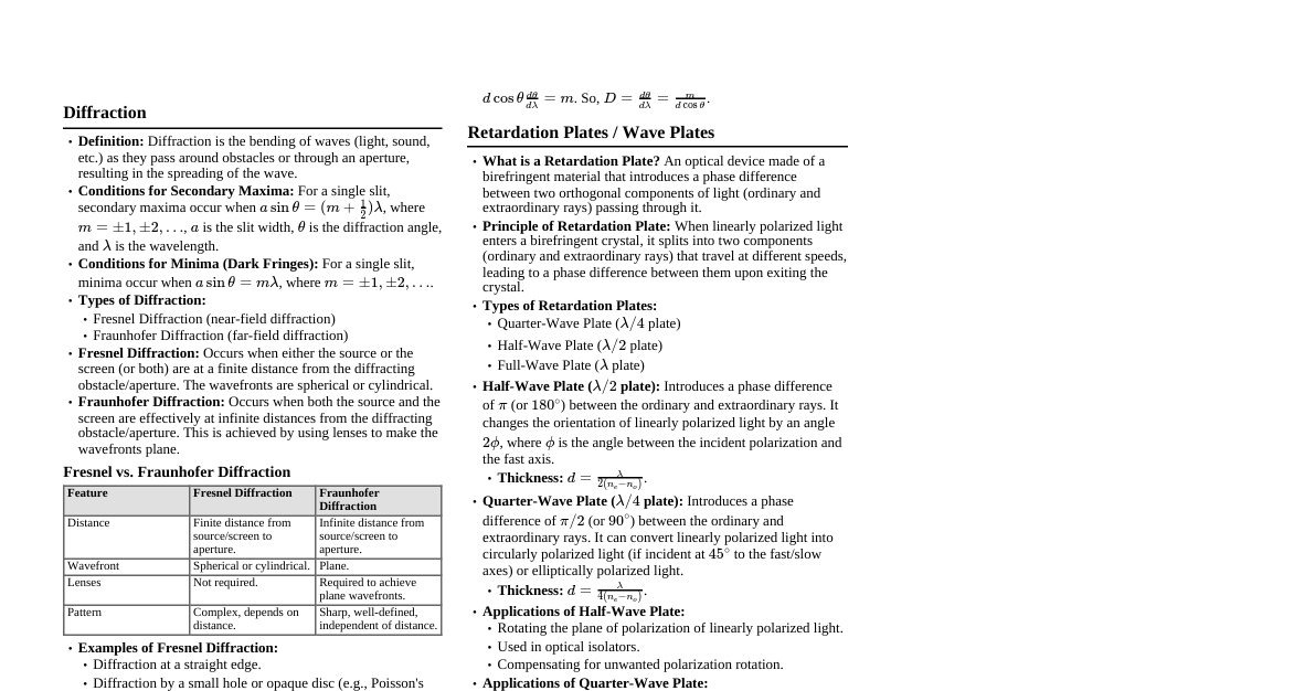
Diffraction of Waves Definition: Spreading of a wave when it passes through a narrow opening (slit) or bending of a wave at the edges of an obstacle. Diffraction is significant when the dimension of the obstacle ($d$) is comparable to the wavelength ($\lambda$) of the wave. If $d > \lambda$: Bending is very less. If $d \approx \lambda$ or $d Importance of Diffraction Diffraction Grating: Acts as a "super prism" for spectral analysis. Resolution of Optical Instruments: Limits the resolving power of telescopes, microscopes, etc. X-Ray Diffractometer: Used in crystallography to determine crystal structures. Electron Microscopes: Utilize electron diffraction for high-resolution imaging. Fraunhofer Diffraction at a Single Slit When a wavefront is obstructed by a slit, diffraction occurs, producing a pattern of maxima and minima. According to Huygens' Explanation: Every point in the slit acts as a source of secondary wavelets. These wavelets propagate and superimpose, forming the diffraction pattern. Intensity at an angle $\theta$: $I_\theta = I_m \left(\frac{\sin\alpha}{\alpha}\right)^2$ Where $\alpha = \frac{\pi a \sin\theta}{\lambda}$ $I_m$ is the maximum intensity at $\theta=0$. $a$ is the slit width, $\lambda$ is the wavelength. Conditions for Maxima and Minima (Single Slit) Type Intensity $\alpha$ Condition Central Maximum $I_m$ $0^\circ$ $\theta = 0^\circ$ Minima $0$ $m\pi$ $a \sin\theta = m\lambda$ (for $m = \pm1, \pm2, ...$) Secondary Maxima Very small $(m + \frac{1}{2})\pi$ $a \sin\theta = (m + \frac{1}{2})\lambda$ (for $m = \pm1, \pm2, ...$) Characteristics of Single Slit Diffraction Results in widening of images. Diffraction depends on wavelength and size of obstacle. Resolving power of electron microscopes is higher than optical microscopes. $\theta \propto \lambda$: Separates different colored light. Can be used as a dispersive device, but its dispersive power is too small. Multiple Slits / Diffraction Grating Used to overcome limitations of single slit diffraction. Maxima become sharper and brighter. Multiple secondary maxima are introduced between principal maxima. For $N$ slits, there are $(N-1)$ minima and $(N-2)$ secondary maxima between principal maxima. Intensity & Conditions for Multiple Slits Intensity at an angle $\theta$: $I_\theta = N^2 I_m \left(\frac{\sin\alpha}{\alpha}\right)^2 \left(\frac{\sin N\beta}{\sin\beta}\right)^2$ Where $\alpha = \frac{\pi a \sin\theta}{\lambda}$ and $\beta = \frac{\pi d \sin\theta}{\lambda}$ $a$: width of individual slit $d$: center-to-center distance between slits ($d = a+b$, where $b$ is the width of opacity) Position of Maxima and Minima (Multiple Slits) Type Intensity $\beta$ Condition Principal Maxima $N^2 I_m \left(\frac{\sin\alpha}{\alpha}\right)^2$ $m\pi$ $d \sin\theta = m\lambda$ (for $m = 0, \pm1, \pm2, ...$) Minima $0$ $m'\pi$ (where $m' \neq mN$) $d \sin\theta = \frac{m'}{N}\lambda$ (for $m' = \pm1, \pm2, ...$ but not multiples of $N$) Diffraction Grating An optical component with a large number of evenly spaced parallel slits (ruling/grooving on transparent material). Disperses composite light into its spectral components (colors) based on wavelength. Scratched parts are opaque, unscratched parts are transparent (act as slits). Grating Element ($d$) $d = 1/N_{lines} = a+b$ $N_{lines}$: Number of lines per unit length. $a$: width of transparent portion. $b$: width of opaque portion. Grating Equation $\sin\theta = n N_{lines} \lambda$ (This seems like a typo, usually $d \sin\theta = n\lambda$ or $(a+b)\sin\theta = n\lambda$) $n$: order of diffraction ($n=1, 2, 3, ...$) $\lambda$: wavelength $\theta$: angle of diffraction The number of orders is limited by $\theta \le 90^\circ$. Properties of Diffraction Grating Dispersive Power ($D$) Ability to produce maximum possible angular separation between two wavelengths ($\Delta\theta / \Delta\lambda$). $D = \frac{d\theta}{d\lambda} = \frac{m}{d\cos\theta} \approx mN_{lines}$ Dispersive power depends on: Directly proportional to the number of lines per unit length ($N_{lines}$). Directly proportional to the order ($m$). Inversely proportional to $\cos\theta$. Smaller the grating element ($d$), larger the angular dispersion. Resolving Power ($RP$) Ability to distinguish between two closely spaced spectral lines. $RP = \frac{\lambda}{\Delta\lambda} = m N_{total}$ $\Delta\lambda$: minimum wavelength difference resolved. $N_{total}$: total number of lines on the grating. Increasing the number of lines (and thus $N_{total}$) increases sharpness and resolution. Rayleigh Criterion Two wavelengths $\lambda$ and $\lambda + \Delta\lambda$ are just resolvable if the principal maximum of one falls on the first minimum of the other. For telescopes and similar instruments: $RP = \frac{1}{\theta_R} = \frac{D}{1.22\lambda}$ $\theta_R$: Rayleigh's angular resolution. $D$: aperture diameter. Interference Thin Film Interference Occurs when light reflects from the top and bottom surfaces of a thin film, leading to superposition. Film thickness ($t$) is typically comparable to the wavelength of light ($\lambda$). Examples: Oil films on water, soap bubbles, anti-reflection coatings. Stoke's Law When light reflects from the surface of an optically denser medium, it undergoes a phase change of $\pi$ (equivalent to a path difference of $\lambda/2$). No phase change occurs when reflected from an optically rarer medium. Path Difference for Thin Films Reflected System: $PD = 2\mu t \cos r \pm \frac{\lambda}{2}$ (The $\pm \lambda/2$ depends on the refractive indices of the surrounding media and the film). Transmitted System: $PD = 2\mu t \cos r$ Conditions for Maxima and Minima (Reflected Light, film surrounded by rarer medium) Constructive Interference (Bright): $2\mu t \cos r = (2n+1)\frac{\lambda}{2}$ (for $n=0, 1, 2, ...$) Destructive Interference (Dark): $2\mu t \cos r = n\lambda$ (for $n=0, 1, 2, ...$) Conditions for Maxima and Minima (Transmitted Light, film surrounded by rarer medium) Constructive Interference (Bright): $2\mu t \cos r = n\lambda$ (for $n=0, 1, 2, ...$) Destructive Interference (Dark): $2\mu t \cos r = (2n+1)\frac{\lambda}{2}$ (for $n=0, 1, 2, ...$) Reflected and transmitted patterns are complementary. Extremely thin ($t \ll \lambda$) or thick ($t \gg \lambda$) films do not produce interference patterns. Fizeau's Fringes Formed in a wedge-shaped film where thickness ($t$) varies gradually, and the angle of refraction ($r$) is constant. Fringes are straight, parallel to the edge of the wedge, and equidistant. Used to measure small angles and surface irregularities. Fringe width: $x_{n+1} - x_n = \frac{\lambda}{2\mu \tan\alpha \cos r}$ (for air wedge, $\mu=1, \cos r \approx 1$, so $\frac{\lambda}{2\alpha}$) Haidinger's Fringes Formed in a thin film of uniform thickness ($t$ constant) where the angle of incidence ($r$ varies). Fringes are concentric circles. Observed at infinity or with a telescope focused for infinity. Newton's Rings An interference pattern formed when a plano-convex lens is placed on a flat glass plate, creating a thin air film of varying thickness. The rings are concentric circles around the point of contact. Path difference: $P.D. = 2\mu t \cos(r+\alpha) \pm \frac{\lambda}{2}$ Diameter of the $n$-th ring: $D_n^2 = \frac{4Rn\lambda}{\mu}$ (for bright rings) or $D_n^2 = \frac{4R(2n+1)\lambda}{2\mu}$ (for dark rings) $R$: radius of curvature of the lens. $n$: order of the ring. $\mu$: refractive index of the film. Characteristics: Complementary in reflected and transmitted light. Rings shift outwards if the lens is lifted. Diameter increases with higher wavelength. Anti-reflection Coatings Thin film (e.g., MgF$_2$, SiO$_2$) coated on a transparent substrate to reduce reflection. Thickness must be $t_{ARC} = \frac{\lambda}{4\mu}$ for destructive interference of reflected light. Anti-transmission Coatings (High Reflection Coatings) Thin film (e.g., TiO$_2$, ZnS) coating to increase reflectivity. Thickness must be $t_{HRC/ATC} = \frac{\lambda}{4\mu}$ for constructive interference of reflected light. Polarization Definition: Restricting the vibrations of a transverse wave to a single plane perpendicular to the direction of propagation. Only transverse waves (like light) can be polarized. Types of Polarized Light Unpolarized Light (UPL): Vibrations occur in all directions perpendicular to propagation. Linearly/Plane Polarized Light (PPL): Vibrations confined to a single plane. Circularly Polarized Light (CPL): Two PPLs of equal amplitude and $\lambda/4$ phase difference, electric vector rotates in a circle. Elliptically Polarized Light (EPL): Two PPLs of unequal amplitude and $\lambda/4$ phase difference, electric vector traces an ellipse. Partially Polarized Light (PRPL): Neither fully polarized nor fully unpolarized. Law of Malus If unpolarized light passes through a polarizer and then an analyzer, the intensity of the transmitted light ($I_\theta$) varies with the angle ($\theta$) between their optic axes. $I_\theta = I_0 \cos^2\theta$ $I_0$: maximum intensity (when axes are parallel, $\theta=0^\circ$). Maximum intensity at $0^\circ, 180^\circ, 360^\circ$. Minimum intensity (zero) at $90^\circ, 270^\circ$. Methods of Producing Polarized Light By Reflection (Brewster's Law): When unpolarized light is incident at Brewster's angle ($i_p$), the reflected light is completely plane-polarized. The reflected and refracted rays are perpendicular ($i_p + r_p = 90^\circ$). Brewster's Angle: $\mu = \tan i_p$ By Pile of Plates: Multiple reflections from a stack of glass plates at Brewster's angle. By Double Refraction: Splitting of unpolarized light into two linearly polarized beams (O-ray and E-ray) whose vibrations are mutually perpendicular. Double Refraction (Birefringence) Occurs in anisotropic crystals (e.g., Calcite, Quartz). Ordinary Ray (O-ray): Obeys Snell's law, constant velocity, spherical wavefront, vibrations perpendicular to optic axis. Extraordinary Ray (E-ray): Does not obey Snell's law, velocity varies with direction, ellipsoidal wavefront, vibrations parallel to optic axis. Uniaxial Crystals: Have one optic axis (e.g., Calcite, Quartz). Negative Crystals (e.g., Calcite): $\mu_O > \mu_E$ (O-ray is slower), $\Delta\mu = \mu_E - \mu_O Positive Crystals (e.g., Quartz): $\mu_E > \mu_O$ (E-ray is slower), $\Delta\mu = \mu_E - \mu_O > 0$. Biaxial Crystals: Have two optic axes (e.g., Mica, Borax). Polarizers & Analyzers Polarizer: An optical device that produces polarized light from unpolarized light. Nicol Prism: Eliminates O-ray via Total Internal Reflection, transmits PPL (E-ray). Polaroids: Eliminate O-ray via selective absorption (dichroism). Tourmaline Crystal: Exhibits dichroism, used as a polarizer. Analyzer: A polarizer used to detect or analyze polarized light. Huygens' Theory of Double Refraction Each point on the refracting surface acts as a source of two secondary wavefronts (O-wavefront and E-wavefront). O-wavefront is spherical, E-wavefront is ellipsoidal. Velocities of O-ray and E-ray are equal along the optic axis. Retardation Plates Doubly refracting uniaxial crystal plates that introduce a phase difference ($\Phi$) between O-ray and E-ray. $\Phi = (\mu_O - \mu_E)t$ (path difference). Quarter Wave Plate (QWP): Introduces a phase difference of $\pi/2$ (path difference $\lambda/4$). Thickness $t = \frac{\lambda}{4(\mu_O - \mu_E)}$ (Negative Crystal) or $t = \frac{\lambda}{4(\mu_E - \mu_O)}$ (Positive Crystal). Converts PPL to CPL/EPL and vice-versa. Half Wave Plate (HWP): Introduces a phase difference of $\pi$ (path difference $\lambda/2$). Thickness $t = \frac{\lambda}{2(\mu_O - \mu_E)}$ (Negative Crystal) or $t = \frac{\lambda}{2(\mu_E - \mu_O)}$ (Positive Crystal). Rotates the plane of polarization of PPL by $2\theta$. Theory of Circularly and Elliptically Polarized Light Superposition of two PPLs (E-ray and O-ray) vibrating in perpendicular directions with a phase difference ($\phi$). Equation of an ellipse: $\frac{x^2}{a^2} + \frac{y^2}{b^2} - \frac{2xy}{ab}\cos\phi = \sin^2\phi$ Resulting Vibration based on Phase Difference ($\phi$) and Amplitudes ($a, b$): $\phi$ Resulting Vibration Remark $0^\circ, 360^\circ$ Straight line ($y = \frac{b}{a}x$) PPL (zero phase difference) $180^\circ$ Straight line ($y = -\frac{b}{a}x$) PPL (180$^\circ$ phase difference) $90^\circ, 270^\circ$ ($a \neq b$) Ellipse ($\frac{x^2}{a^2} + \frac{y^2}{b^2} = 1$) EPL (unequal amplitudes, $90^\circ$ phase difference) $90^\circ, 270^\circ$ ($a = b$) Circle ($x^2 + y^2 = a^2$) CPL (equal amplitudes, $90^\circ$ phase difference) Applications of Polarization Polarizing Sunglasses: Reduce glare by blocking horizontally polarized light. Optical Activity: Certain materials (e.g., sugar solution, quartz) rotate the plane of PPL. Angle of rotation ($\theta$) depends on concentration ($c$), length of cell ($l$), and specific rotation ($S$): $\theta = Slc$. Measured by a Saccharimeter. Liquid Crystal Displays (LCDs): Utilize the ability of liquid crystals to rotate polarized light when an electric field is applied. 3-D Movies: Use perpendicularly polarized light for left and right eye images, viewed through polarizing glasses. Photo-Elasticity: Analyzes stress distributions in materials by observing changes in polarization when materials become double refracting under stress. Radars: Bigger antennas and multi-antenna radars use precise control of diffraction effects for better resolution. X-ray Diffraction: Used for material characterization.