BJT Cheatsheet
Cheatsheet Content
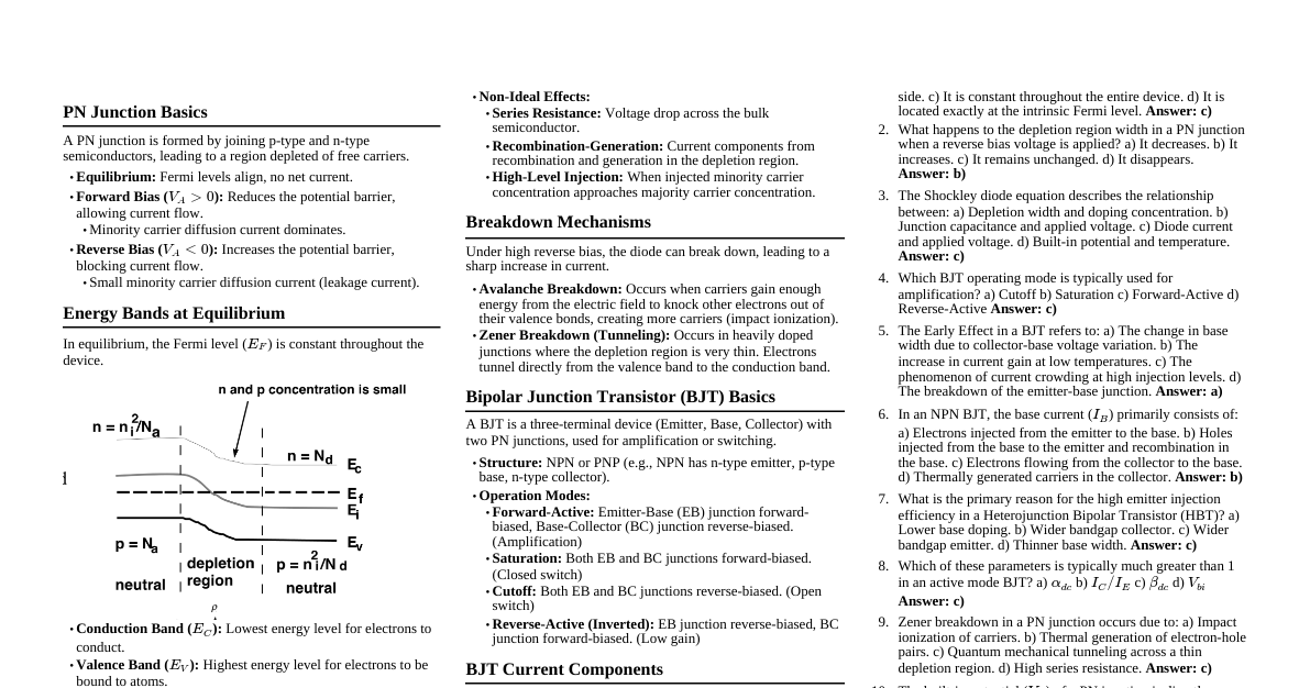
Bipolar Junction Transistors (BJT) Definition: Three-terminal semiconductor devices used to amplify signals. The term "bipolar" means both holes and electrons participate in the injection process. Developed by Walter H. Brattain and John Bardeen at Bell Telephone Laboratories on December 23, 1947. Advantages: Smaller and lightweight No heater requirements (unlike vacuum tubes) More power efficient (less power absorption, no heating element) Rugged construction, less prone to damage Operates upon power-up (no warm-up needed) Operates with lower voltages Cheaper due to abundant and less expensive materials BJT Types and Structure Two basic types: NPN and PNP transistors. Can be constructed using Silicon, Germanium, or GaAs. Three layers/terminals: Emitter (E): Heavily doped. Base (B): Lightly doped. Collector (C): Lightly doped. Less doped material has less conductivity or higher resistance. Emitter and collector layers are wider than the base layer. BJT Operation Principles Construction similar to two diodes with connected anodes/cathodes, but operation is different. Majority carriers: Electrons in n-type material, holes in p-type material. Biasing: Emitter-base (EB) and collector-base (CB) junctions can be forward or reverse biased depending on application. Conventional Current: The arrow in the emitter symbol indicates the direction of conventional current flow. NPN Transistor (Biasing Example) N P N Emitter (E) Collector (C) Base (B) Emitter-base junction Collector-base junction C E B When EB junction is forward biased and CB junction is reverse biased: Electron flow (majority carrier) from emitter to base. Base layer is very thin and has low conductivity, so most electrons move into the collector layer. Emitter current ($I_E$) is almost equal to collector current ($I_C$), and base current ($I_B$) is relatively low. $I_E = I_B + I_C$ $I_E \approx I_C$ (typically $I_B$ is in microamperes, $I_E$ and $I_C$ in milliamperes). PNP Transistor (Biasing Example) P N P Emitter (E) Collector (C) Base (B) Emitter-base junction Collector-base junction C E B When EB junction is forward biased and CB junction is reverse biased: Hole flow (majority carrier) from emitter to base. Base layer is very thin and has low conductivity, so most holes move into the collector layer. Emitter current ($I_E$) is almost equal to collector current ($I_C$), and base current ($I_B$) is relatively low. $I_E = I_B + I_C$ $I_E \approx I_C$ Currents in BJT Electron flow vs. Conventional current: Electron flow is opposite to conventional current flow. Emitter current ($I_E$): Sum of base current ($I_B$) and collector current ($I_C$). $$I_E = I_B + I_C \approx I_C$$ Base current ($I_B$): Typically in microamperes. Collector current ($I_C$): Comprised of majority and minority carriers. Leakage current ($I_{CO}$): Collector current due to minority carriers. $$I_C = I_{C, majority} + I_{C, minority} = I_{C, majority} + I_{CO}$$ $I_{CO}$ is present even without EB voltage if CB voltage with indicated polarity is applied. $I_{CO}$ is temperature sensitive and increases with temperature. Common Base Transistor Configuration One of three common configurations (common base, common emitter, common collector). Each has unique characteristics, advantages, and disadvantages. Common Terminal: Base is common to both input ($V_i$) and output ($V_o$), often connected to ground. Input: Between base and emitter. Output: Between base and collector. Input usually on left side, output on right side of circuit diagram. Biasing: Base-emitter junction is forward biased, collector-base junction is reverse biased. Input Characteristic Curve (Common Base) Relates input current ($I_E$) and input voltage ($V_{BE}$) for various output voltages ($V_{CB}$). $I_E$ (mA) $V_{BE}$ (V) Reverse biased Base-emitter junction forward biased Knee voltage $V_{CB}$=20 V $V_{CB}$=10 V $V_{CB}$=1 V 0.2 0.4 Resembles a diode characteristic curve. $V_{CB}$ has a small effect on $I_E$. Output Characteristic Curve (Common Base) Relates output current ($I_C$), output voltage ($V_{CB}$), and input current ($I_E$). $I_C$ (mA) $V_{CB}$ (Volts) Saturation region Active region Cutoff region $I_E$ = 14 mA $I_E$ = 12 mA $I_E$ = 10 mA $I_E$ = 8 mA $I_E$ = 6 mA $I_E$ = 4 mA $I_E$ = 2 mA $I_E$ = 0 DC load line $I_C$ is approximately equal to $I_E$. When $I_E = 0$, $I_C$ equals the reverse saturation current for common base ($I_{CBO}$), due to minority carriers. Operating Regions (Common Base) Active region: Emitter-base junction: Forward biased. Collector-base junction: Reverse biased. $I_E \approx I_C$. As $I_E$ increases, $I_C$ increases by approximately the same amount. $V_{BE}$ is approx. 0.7 V for Si, 0.3 V for Ge, 1.2 V for GaAs. $V_{CB}$ has negligible effect on $I_C$. Lower boundary: $I_E = 0$ and $I_C = I_{CBO}$. $I_{CBO}$ is usually very small (nanoamperes for low/mid power, microamperes for high power). $I_{CBO}$ is temperature sensitive. Used for linear amplification (output waveform similar to input). Saturation region: Defined by $V_{CB} \le 0$. Emitter-base junction: Forward biased. Collector-base junction: Forward biased. Cutoff region: Collector current is practically zero ($I_C = I_{CBO}$). Emitter-base junction: Reverse biased. Collector-base junction: Reverse biased. Transistors can switch between saturation and cutoff (digital applications). Alpha ($\alpha$) Parameter (Common Base) DC mode ($\alpha_{dc}$): Relates output current ($I_C$) and input current ($I_E$). $$\alpha_{dc} = \frac{I_C}{I_E} = \text{common base DC current gain}$$ $\alpha_{dc}$ is always less than 1 but approximately equal to 1. Typical values: 0.9 to 0.998. $\alpha_{dc}$ can vary slightly at different operating points (not perfectly linear). $\alpha_{dc}$ is defined for majority carriers. Considering minority carriers: $$I_C = \alpha_{dc} I_E + I_{CBO}$$ where $I_{CBO}$ is the collector leakage current when $I_E = 0$. AC mode ($\alpha_{ac}$): Relates change in output current ($\Delta I_C$) and change in input current ($\Delta I_E$) at constant $V_{CB}$. $$\alpha_{ac} = \frac{\Delta I_C}{\Delta I_E} \Big|_{V_{CB}=\text{constant}} = \text{common base, short circuit amplification factor}$$ $\alpha_{ac}$ is used for amplifying AC signals. For most situations, $\alpha_{dc} \approx \alpha_{ac}$. Amplifiers A device or circuit that increases the amplitude of a signal (voltage, current, or both). Can amplify input voltage, input current, or input power. Gain is the ratio of output signal to input signal. Voltage Gain ($A_v$): $$A_v = \frac{V_o}{V_i} = \frac{\text{Output Voltage}}{\text{Input Voltage}}$$ Current Gain ($A_i$): $$A_i = \frac{I_o}{I_i} = \frac{\text{Output Current}}{\text{Input Current}}$$ Power Gain ($A_p$): $$A_p = \frac{P_o}{P_i} = \frac{\text{Output Power}}{\text{Input Power}}$$ Relationship between gains: $$A_p = \frac{P_o}{P_i} = \frac{V_o I_o}{V_i I_i} = A_v A_i$$ Multi-stage amplifiers: Overall gain is the product of individual stage gains. $$A_{vT} = A_{v1} A_{v2} \cdots A_{vn}$$ $$A_{iT} = A_{i1} A_{i2} \cdots A_{in}$$ Common Base Transistor Amplifier (NPN) E C B $I_E, I_C, I_B$ have DC and AC components. Only DC components are present without AC input signal ($V_s$). $V_{BE}, V_{CE}, V_{CB}$ voltages also have DC and AC components. Input AC current ($I_i$) = AC emitter current ($I_e$). Output AC current ($I_o$) = AC collector current ($I_c$). Input impedance ($Z_i$) and Output impedance ($Z_o$). Capacitor $C_1$ eliminates DC component of voltage between collector and base; $V_o$ only includes AC component of $V_{CB}$. Impedance of capacitor: $Z_c = \frac{1}{j2\pi fC}$. For DC signals ($f=0$), $Z_c = \infty$. Capacitors pass AC signals and block DC signals. Quiescent Conditions (Common Base) When input signal ($V_s$) is 0 (no AC input signal), only DC voltages and currents are present. $I_{EQ}, I_{CQ}, I_{BQ}$ are quiescent emitter, collector, and base currents. $V_{BEQ}, V_{CEQ}, V_{CBQ}$ are quiescent base-emitter, collector-emitter, and collector-base voltages. 'Q' stands for quiescent (no input AC signal). $I_{EQ} = I_{BQ} + I_{CQ} \approx I_{CQ}$. $V_{BEQ}$ is typically 0.7 V (Si), 0.3 V (Ge), 1.2 V (GaAs). $V_{CEQ} = V_{BEQ} + V_{CBQ}$. AC Signal Operation (Common Base) Input signal ($V_s$) adds to or subtracts from DC supply voltage ($V_{EE}$). Varying input voltage causes changes in emitter current, collector current, base-collector voltage, and emitter-collector voltage. During positive half of input signal: $V_{AB}$ decreases, $I_E$ decreases, $I_C$ decreases, $V_{RC}$ decreases, $V_{CB}$ increases, $V_o$ increases (becomes more positive). Output voltage ($V_o$) is in phase with input signal ($V_s$). Common Base Transistor Amplifier Characteristics Low input impedance ($Z_i$): Typically 10 to 100 ohms. High output impedance ($Z_o$): Typically 50 kohm to megaohm range. AC current gain ($A_i(ac)$): $$A_i(ac) = \frac{I_c}{I_e} = \alpha_{ac} \approx 1$$ DC current gain ($A_i(dc)$): $$A_i(dc) = \frac{I_C}{I_E} = \alpha_{dc} \approx 1$$ Voltage gain ($A_v$): $$A_v = \frac{V_o}{V_i} = \frac{V_{cb}}{V_{be}} \approx \frac{\alpha_{ac} R_c}{Z_i}$$ If $R_c$ is significantly larger than $Z_i$, $A_v > 1$. Output voltage is in phase with input voltage. Voltage amplifying action is achieved by transferring current from low resistance ($Z_i$) to high resistance circuit.