Machine Design: Shafts
Cheatsheet Content
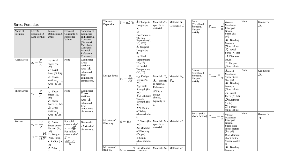
### Shaft Basics & Materials | Feature | Description | Common Materials | | :------------ | :------------------------------------------------------------------------------------------------------ | :-------------------------------------------------------------------------------------------------------------------------------- | | **Definition** | Rotating machine element transmitting power. | Carbon steel (C45, C50), Alloy steel (40Cr1, 35Ni1Cr60). | | **Types** | **Transmission:** General power transfer. **Machine:** Integral to specific machines (e.g., crankshafts). | High strength, good machinability, good heat treat response, low notch sensitivity. | ### Stress Formulas | Stress Type | Solid Circular Shaft | Hollow Circular Shaft | Notes | | :----------------- | :-------------------------------------------------------- | :---------------------------------------------------------------------------------- | :------------------------------------------------------------------ | | **Torsional Shear** | $\tau = \frac{16T}{\pi d^3}$ | $\tau = \frac{16T}{\pi d_o^3 (1 - k^4)}$ where $k = d_i/d_o$ | $T$: Torque, $d$: diameter, $d_o$: outer, $d_i$: inner. | | **Bending Normal** | $\sigma_b = \frac{32M}{\pi d^3}$ | $\sigma_b = \frac{32M}{\pi d_o^3 (1 - k^4)}$ | $M$: Bending Moment. | | **Axial (if any)** | $\sigma_a = \frac{F}{A}$ | $A = \frac{\pi}{4}(d_o^2 - d_i^2)$ | $F$: Axial Force, $A$: Cross-sectional Area. Usually negligible. | ### Combined Stresses & Failure Theories | Theory | Material Type | Equivalent Stress / Design Formula | | :----------------------------------- | :------------ | :--------------------------------------------------------------------------------------------------------------------------------------------------------------------------------------------- | | **Max Shear Stress (Tresca/Guest)** | Ductile | $$ \tau_{eq} = \sqrt{\left(\frac{\sigma_b}{2}\right)^2 + \tau^2} $$ $$ d^3 = \frac{16}{\pi \tau_{allow}} \sqrt{M^2 + T^2} $$ | | **Max Normal Stress (Rankine)** | Brittle | $$ \sigma_{eq} = \frac{1}{2} \left[ \sigma_b + \sqrt{\sigma_b^2 + 4\tau^2} \right] $$ $$ d^3 = \frac{32}{\pi \sigma_{allow}} \left[ \frac{M + \sqrt{M^2 + T^2}}{2} \right] $$ | ### Design Criteria | Criterion | Description | Formulas / Guidelines | | :---------------- | :------------------------------------------------------------------- | :---------------------------------------------------------------------------------------------------------------------------------------------------------------------------------------------------------------------------------------------- | | **1. Strength** | Withstand static/fatigue loads without yielding/fracture. | **Allowable Shear:** $\tau_{allow} = 0.3 S_{yt}$ or $0.18 S_{ut}$ (no keyway) $\tau_{allow} = 0.75 \times (0.3 S_{yt})$ (with keyway) ($S_{yt}$: Yield Strength, $S_{ut}$: Ultimate Strength) | | **2. Rigidity** | Prevent excessive deflection/twist. | **Torsional Twist ($\theta$):** $$ \theta = \frac{TL}{GJ} $$ $J_{solid} = \frac{\pi d^4}{32}$, $J_{hollow} = \frac{\pi (d_o^4 - d_i^4)}{32}$ Permissible Twist: $\approx 0.25^\circ$ per meter. | | | | **Lateral Deflection ($\delta$):** Beam deflection formulas. Permissible Deflection: $0.0002L$ (gears), $0.00025L$ (bearings). | ### Fatigue Design for Fluctuating Loads | Concept | Description | Formulas / Considerations | | :---------------------- | :------------------------------------------------------------------------------ | :------------------------------------------------------------------------------------------------------------------------------------------------------------------------------------------------------------------------------------------------------------------------------------------------- | | **Endurance Limit** ($S_e$) | Max stress shaft can withstand for infinite cycles without failure. | $S_e = S_e' \cdot C_L \cdot C_G \cdot C_S \cdot C_M \cdot C_{SF}$ $S_e' \approx 0.5 S_{ut}$ (for $S_{ut} \le 1400$ MPa) $C_L$: Load Factor, $C_G$: Size Factor, $C_S$: Surface Factor, $C_M$: Temp Factor, $C_{SF}$: Stress Concentration Factor. | | **Stress Concentration** | Localized stress increase at geometric discontinuities. | $K_f = 1 + q(K_t - 1)$ $K_f$: Fatigue Stress Concentration Factor, $q$: Notch Sensitivity, $K_t$: Theoretical Stress Concentration Factor. | | **Fatigue Criteria** | Predict failure under fluctuating mean ($\sigma_m$) and alternating ($\sigma_a$) stresses. | **Soderberg (conservative):** $$ \frac{1}{FOS} = \frac{\sigma_m}{S_{yt}} + \frac{\sigma_a}{S_e} $$ **Modified Goodman (common):** $$ \frac{1}{FOS} = \frac{\sigma_m}{S_{ut}} + \frac{\sigma_a}{S_e} \left( \frac{S_{ut} - S_e}{S_{ut}} \right) $$ $FOS$: Factor of Safety. | ### Critical Speed ($N_c$) | Concept | Description | Formulas | | :------------- | :------------------------------------------------------------------------------------------------------- | :------------------------------------------------------------------------------------------------------------------------------------------------------------------------------------------------------------------------------------- | | **Definition** | Rotational speed matching shaft's natural vibration frequency, leading to resonance and large vibrations. | **Single Concentrated Load:** $$ N_c = \frac{60}{2\pi} \sqrt{\frac{g}{\delta_{max}}} \text{ rpm} $$ $g$: acceleration due to gravity, $\delta_{max}$: max static deflection. **Dunkerley's (multiple loads):** $$ \frac{1}{(N_c)^2} = \sum_{i=1}^n \frac{1}{(N_i)^2} $$ | | **Design Note** | Operating speed must be well away from $N_c$. | | ### Shaft Components & Features | Feature | Purpose | Design Consideration | | :------------- | :------------------------------------------------------------------------------------------------------ | :--------------------------------------------------------------------------------------------------------------------------------------------------------------------------------------------------------------------------- | | **Keyways** | Transmit torque using keys between shaft and hub. | Significant stress concentrators; reduce shaft strength (e.g., $0.75 \times \tau_{allow}$). | | **Shoulders** | Change in diameter to locate components (bearings, gears). | Introduce stress concentration; require proper fillet radii. | | **Fillets** | Radii at shoulder junctions. | Reduce stress concentration caused by abrupt changes in cross-section. Larger radius = lower stress concentration. | | **Splines** | Multiple integral keys; provide better torque transmission and alignment than single keyways. | Higher torque capacity; less stress concentration than keyways for the same torque. | | **Couplings** | Connect two shafts to transmit power. | Selection depends on alignment, torque, speed, and vibration. | | **Bearings** | Support the shaft, reduce friction during rotation. | Type (ball, roller, plain) depends on load, speed, accuracy, and rigidity requirements. Proper lubrication is crucial. |