Computer System Architecture (R21)
Cheatsheet Content
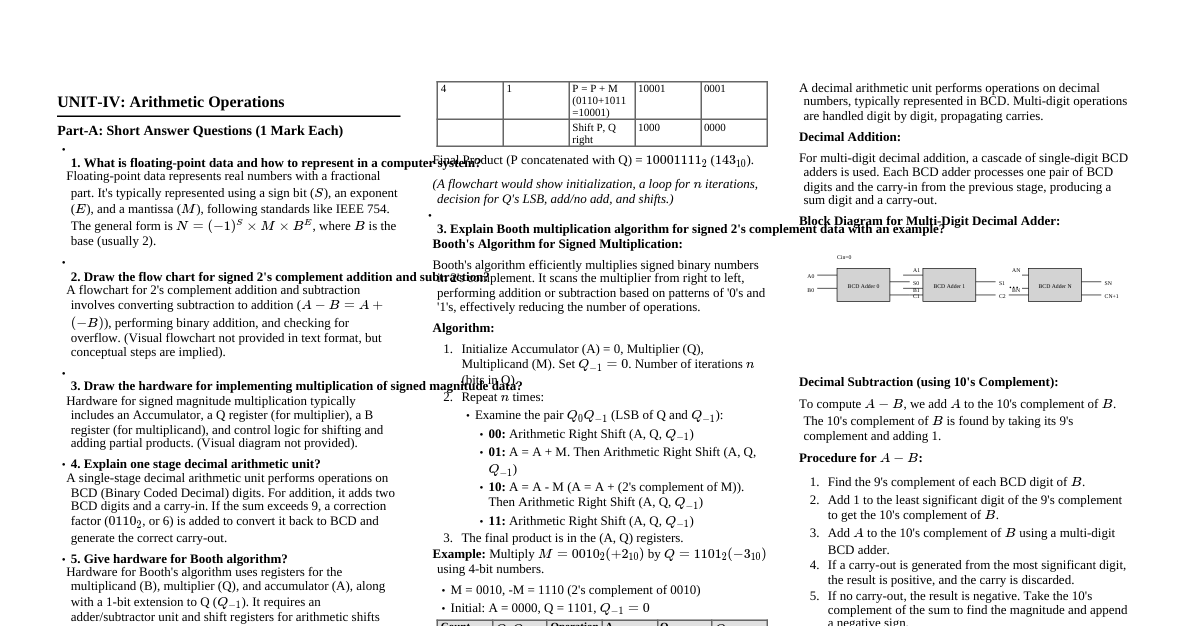
UNIT-I: Data Representation and Digital Logic Part-A: Basic Concepts (1 Mark Focus) Self-Complementary Codes: A code where the 9's complement of a decimal digit is obtained by complementing each bit of the code word. Examples: 2421, 5211, Excess-3. Not BCD. Binary to Gray Code Conversion: MSB of Gray code is same as MSB of Binary. From left to right, add each binary bit to the next binary bit, ignoring carries, to get the next Gray code bit. Example: Binary $1011010_2$ $G_6 = B_6 = 1$ $G_5 = B_6 \oplus B_5 = 1 \oplus 0 = 1$ $G_4 = B_5 \oplus B_4 = 0 \oplus 1 = 1$ $G_3 = B_4 \oplus B_3 = 1 \oplus 1 = 0$ $G_2 = B_3 \oplus B_2 = 1 \oplus 0 = 1$ $G_1 = B_2 \oplus B_1 = 0 \oplus 1 = 1$ $G_0 = B_1 \oplus B_0 = 1 \oplus 0 = 1$ Result: $1110111_G$ Excess-3 Code: A self-complementary BCD code obtained by adding $3 (0011_2)$ to each BCD digit. Example: Binary $1011010_2$ (This is a binary number, not BCD. Assuming it converts to decimal first for Excess-3) $1011010_2 = 64+16+8+2 = 90_{10}$. BCD for 90: $1001 \ 0000$. Excess-3 for 90: $(1001+0011) \ (0000+0011) = 1100 \ 0011_{XS3}$. Decimal to Binary, Octal, Hexadecimal Conversion: Binary: Repeated division by 2, collect remainders from bottom up. Octal: Repeated division by 8, collect remainders. Hexadecimal: Repeated division by 16, collect remainders (A-F for 10-15). Example: $438_{10}$ Binary: $438/2 = 219 R 0$, $219/2 = 109 R 1$, ..., $438_{10} = 110110110_2$ Octal: $438/8 = 54 R 6$, $54/8 = 6 R 6$, $6/8 = 0 R 6$. $438_{10} = 666_8$ Hexadecimal: $438/16 = 27 R 6$, $27/16 = 1 R 11 (B)$, $1/16 = 0 R 1$. $438_{10} = 1B6_{16}$ Binary Addition: $0+0=0$ $0+1=1$ $1+0=1$ $1+1=0$ (carry 1) Example i) $1000101_2 + 0110101_2$ ``` 1000101 + 0110101 --------- 1111010 ``` Example ii) $1110_2 + 0110_2$ ``` 1110 + 0110 --------- 10100 ``` 2421 Code: A weighted BCD code where weights are 2, 4, 2, 1. It is a self-complementing code. Decimal 2421 Code 0 0000 1 0001 2 0010 3 0011 4 0100 5 1011 6 1100 7 1101 8 1110 9 1111 Part-B: Advanced Operations (10 Marks Focus) Binary Subtraction using Complements: 1's Complement: To subtract $B$ from $A$: Find 1's complement of $B$. Add 1's complement of $B$ to $A$. If there is an end carry, add it to the LSB (end-around carry). Result is positive. If no end carry, result is negative; find 1's complement of the sum. 2's Complement: To subtract $B$ from $A$: Find 2's complement of $B$ (1's complement + 1). Add 2's complement of $B$ to $A$. If there is an end carry, discard it. Result is positive. If no end carry, result is negative; find 2's complement of the sum. Example: $1011_2 - 1001_2$ using 2's complement (assuming 4-bit numbers) $A = 1011_2$, $B = 1001_2$. 2's complement of $B$: $0110_2$ (1's comp) $+ 1 = 0111_2$. $A + (2's \ comp \ of \ B) = 1011_2 + 0111_2 = 10010_2$. Discard end carry (the leading 1). Result: $0010_2$. BCD Subtraction: Typically performed using 9's or 10's complement of BCD numbers. 9's Complement: For each decimal digit, subtract it from 9, then convert to BCD. Add $0011_2$ to each BCD digit and discard carry. 10's Complement: 9's complement + 1. After BCD addition, if sum of 4 bits exceeds 9 ($>1001_2$), or if there's a carry-out, add $6 (0110_2)$ to that group and propagate carry to the next group. Example: $786_{10} - 348_{10}$ $A = 786$, $B = 348$. 9's complement of $B = 999 - 348 = 651$. Add $A + (9's \ comp \ of \ B) = 786 + 651 = 1437$. End-around carry (1) means result is positive. Add 1 to the result: $437+1 = 438$. Convert to BCD: $0100 \ 0011 \ 1000_{BCD}$. Number Base Conversions: $(101010)_2 = 32+8+2 = 42_{10}$ $(764)_8 = 7 \cdot 8^2 + 6 \cdot 8^1 + 4 \cdot 8^0 = 7 \cdot 64 + 6 \cdot 8 + 4 = 448 + 48 + 4 = 500_{10}$. To Hex: $500/16 = 31 R 4$, $31/16 = 1 R 15 (F)$, $1/16 = 0 R 1$. So $1F4_{16}$. $(ED6)_{16} = E \cdot 16^2 + D \cdot 16^1 + 6 \cdot 16^0 = 14 \cdot 256 + 13 \cdot 16 + 6 = 3584 + 208 + 6 = 3798_{10}$. To Octal: Convert to binary first: $1110 \ 1101 \ 0110_2$. Group into 3 bits: $111 \ 011 \ 010 \ 110_2 = 7326_8$. $(547)_{10}$. To Binary: $547/2 = 273 R 1$, etc. $547_{10} = 1000100011_2$. Binary to Gray Code & Excess-3 Conversion (revisited): $(101011)_2$: Gray Code: $111110_G$. Excess-3 (first convert to decimal as $43_{10}$): $0100 \ 0011_{BCD} \rightarrow 0111 \ 0110_{XS3}$. $(110110)_2$: Gray Code: $101101_G$. Excess-3 (first convert to decimal as $54_{10}$): $0101 \ 0100_{BCD} \rightarrow 1000 \ 0111_{XS3}$. Code Tables (8421, 2421, Gray, Excess-3 for 0-15): Decimal Binary 8421 BCD 2421 Code Gray Code Excess-3 0 0000 0000 0000 0000 0011 1 0001 0001 0001 0001 0100 2 0010 0010 0010 0010 0101 3 0011 0011 0011 0011 0110 4 0100 0100 0100 0100 0111 5 0101 0101 1011 0111 1000 6 0110 0110 1100 0110 1001 7 0111 0111 1101 0101 1010 8 1000 1000 1110 1101 1011 9 1001 1001 1111 1100 1100 10 1010 N/A N/A 1110 N/A 11 1011 N/A N/A 1111 N/A 12 1100 N/A N/A 1011 N/A 13 1101 N/A N/A 1010 N/A 14 1110 N/A N/A 1001 N/A 15 1111 N/A N/A 1000 N/A Note: BCD and Excess-3 are for individual digits 0-9. For numbers > 9, they are represented digit by digit. UNIT-II: Basic Computer Organization and Design Part-A: Basic Concepts (1 Mark Focus) Shift Micro-operations: Operations that shift the bits of a binary word (register) left or right. Types: Logical Shift: Shifts bits, fills empty positions with 0. Arithmetic Shift: Preserves sign bit, used for signed numbers. Circular Shift (Rotate): Bits shifted out one end are shifted in the other end. Register Transfer Language (RTL): A symbolic notation used to describe the micro-operations of a digital system. It provides a formal way to express the transfer of data between registers and the operations performed on that data. Types of Computers: Microcomputers (PCs, laptops) Minicomputers (small servers) Mainframes (large-scale transaction processing) Supercomputers (high-performance computing) Embedded Systems (specialized, e.g., in appliances) Functions of Control Unit: Fetches instructions from memory. Decodes instructions. Manages and coordinates components of the computer (ALU, registers, I/O). Generates control signals to execute instructions. Von Neumann Architecture: A computer architecture based on a stored-program concept where instruction program memory and data memory share the same address space and data path (single bus). Key features: Single address space for instructions and data. Sequential instruction execution. Fetch-decode-execute cycle. 4-bit Binary Incrementer: A combinational circuit that adds 1 to a 4-bit binary number. It can be built using half-adders and full-adders or simply cascading XOR gates for sum and AND gates for carry propagation. Part-B: Advanced Explanations (10 Marks Focus) Functional Units of a Computer: Input Unit: Takes data and instructions from the outside world (keyboard, mouse). Output Unit: Presents processed results to the user (monitor, printer). Memory Unit: Stores data and instructions (RAM, ROM). Arithmetic Logic Unit (ALU): Performs arithmetic (+, -, *, /) and logical (AND, OR, NOT) operations. Control Unit (CU): Directs and coordinates all operations within the computer. These units work together under the control of the CU to execute programs. Common Bus Structure: A shared communication pathway that connects multiple components (CPU, memory, I/O). Multiplexers (MUX): Used to select which register's output is placed on the bus. Each register has its output connected to a MUX input, and the MUX's select lines determine which register's data passes through to the bus. Three-State Buffers: Devices with three output states: HIGH, LOW, and high-impedance (effectively disconnected). Multiple three-state buffers can share a single line (the bus). Only one buffer is enabled at a time to drive the bus, while others are in high-impedance state. Arithmetic Micro-operations: Operations performed by the ALU on numeric data stored in registers. Addition: $R_1 \leftarrow R_2 + R_3$ Subtraction: $R_1 \leftarrow R_2 - R_3$ (often implemented as $R_2 + \text{2's complement of } R_3$) Increment: $R_1 \leftarrow R_1 + 1$ Decrement: $R_1 \leftarrow R_1 - 1$ Multiply/Divide (can be more complex, involving sequences of shifts and adds/subtracts). These are fundamental building blocks for complex arithmetic instructions. Fixed and Floating Point Number Representation: Fixed-Point: Binary point is assumed to be in a fixed position. Integral and fractional parts are stored. Signed Magnitude: MSB for sign (0=pos, 1=neg), rest for magnitude. Example: $+5 = 0101$, $-5 = 1101$. 1's Complement: Negatives are 1's complement of positives. Example: $+5 = 0101$, $-5 = 1010$. 2's Complement: Most common. Negatives are 2's complement of positives. Example: $+5 = 0101$, $-5 = 1011$. Advantages: Simple hardware. Disadvantages: Limited range, precision issues. Floating-Point: Represents numbers as $M \times B^E$ (Mantissa $\times$ Base$^{\text{Exponent}}$). Similar to scientific notation. Typically uses IEEE 754 standard (single-precision 32-bit, double-precision 64-bit). Format: Sign bit (S), Exponent (E), Mantissa/Fraction (M). Value $= (-1)^S \times (1.M) \times 2^{E - Bias}$. Advantages: Wide dynamic range, handles very large/small numbers. Disadvantages: More complex hardware, potential for precision loss. 4-bit Binary Adder and Subtractor: Adder: A circuit that performs binary addition. A 4-bit adder can be constructed by cascading four full-adder circuits. Each full-adder takes three inputs (two bits to be added and a carry-in) and produces two outputs (sum and carry-out). Subtractor: Can be implemented using an adder by taking the 2's complement of the subtrahend and adding it to the minuend. A 4-bit adder/subtractor unit often includes an XOR gate for each bit of the subtrahend, controlled by a "subtract" signal. If subtract is 0, XOR passes the bit; if 1, it inverts the bit (1's complement), and a carry-in of 1 is provided for 2's complement. UNIT-III: Central Processing Unit Part-A: Basic Concepts (1 Mark Focus) Data Manipulation Instructions: Instructions that perform operations on data, such as arithmetic (add, subtract, multiply, divide), logical (AND, OR, XOR, NOT), and shift (logical, arithmetic, rotate). Instruction Set Completeness: Refers to whether an instruction set contains enough instructions to perform any computationally expressible task. A complete instruction set should include: Data transfer instructions. Arithmetic and logical operations. Program control instructions (branch, jump). Input/Output instructions. Instruction Cycle: The basic cycle that a CPU follows to execute an instruction. It typically consists of: Fetch: Retrieve instruction from memory. Decode: Interpret the instruction. Execute: Perform the operation specified by the instruction. Write-back: Store the result (optional, or part of execute). Program Interrupt: A mechanism by which other modules (I/O, memory) or software can interrupt the normal processing of the CPU. It is a signal to the processor to temporarily stop its current execution and handle an event. Types of Interrupts: Hardware Interrupts: From I/O devices (e.g., keyboard press, disk read completion). Software Interrupts: Caused by program execution (e.g., system calls, errors like division by zero). Timer Interrupts: Generated by a timer to perform periodic tasks. Stack Organizations: Register Stack: A stack implemented using a set of CPU registers. Fast but limited in size. Memory Stack: A stack implemented in main memory. Slower but allows for larger stack sizes. A stack pointer register (SP) points to the top of the stack. CISC vs. RISC: CISC (Complex Instruction Set Computer): Large instruction set. Complex instructions, often performing multiple operations. Variable instruction formats. Microprogrammed control unit. Example: Intel x86. RISC (Reduced Instruction Set Computer): Small, highly optimized instruction set. Simple, single-cycle instructions. Fixed instruction formats. Hardwired control unit. Emphasis on register-to-register operations. Example: ARM, MIPS. Part-B: Advanced Explanations (10 Marks Focus) Program to evaluate $X=(A+B)*(C+D)$ using different addressing instructions: (This would require a specific instruction set architecture, e.g., an accumulator-based machine, stack-based, or general-purpose register machine. A general register machine example): ```assembly ; Assume A, B, C, D are in memory locations ; Assume R1, R2, R3, R4 are general purpose registers LOAD R1, A ; R1 Registers of a Basic Computer and Common Bus System: Registers: Program Counter (PC): Holds address of the next instruction. Accumulator (AC): General purpose register for arithmetic/logic. Instruction Register (IR): Holds the instruction currently being executed. Memory Address Register (AR): Holds address for memory access. Memory Buffer Register (DR/MBR): Holds data read from/written to memory. Temporary Register (TR): For temporary data storage during operations. Input Register (INPR): Holds input character. Output Register (OUTR): Holds output character. Common Bus System: These registers are connected to a common bus. Control signals from the control unit determine which register places its data onto the bus (source) and which register loads data from the bus (destination). This allows efficient data transfer between components. For example, to move data from DR to AC, a control signal enables DR to output to the bus, and another control signal enables AC to load from the bus. Instruction Formats: Define the layout of bits in an instruction. Zero-Address (Stack-based): Operands are implicitly on top of the stack. E.g., `ADD` pops two, adds, pushes result. One-Address (Accumulator-based): One operand is implicitly the accumulator. E.g., `ADD B` means $AC \leftarrow AC + [B]$. Two-Address: Two explicit operands. E.g., `ADD R1, R2` means $R1 \leftarrow R1 + R2$. Three-Address: Three explicit operands (source1, source2, destination). E.g., `ADD R1, R2, R3` means $R1 \leftarrow R2 + R3$. Each format has trade-offs in instruction length, code density, and complexity of CPU design. Addressing Modes: Ways to specify the operand of an instruction. Immediate: Operand is part of the instruction itself. E.g., `ADD R1, #5` ($R1 \leftarrow R1 + 5$). Register: Operand is in a CPU register. E.g., `ADD R1, R2` ($R1 \leftarrow R1 + R2$). Direct (Absolute): Operand's memory address is in the instruction. E.g., `LOAD R1, 1000H` ($R1 \leftarrow M[1000H]$). Indirect: Instruction contains address of a memory location that holds the effective address of the operand. E.g., `LOAD R1, (1000H)` ($R1 \leftarrow M[M[1000H]]$). Register Indirect: Register holds the effective address. E.g., `LOAD R1, (R2)` ($R1 \leftarrow M[R2]$). Indexed: Effective address is (base address + index register content). E.g., `LOAD R1, 100(R2)` ($R1 \leftarrow M[100 + R2]$). Relative: Effective address is (PC content + displacement). Used for position-independent code. These modes offer flexibility in accessing data and memory. Register Stack, Memory Stack, Reverse Polish Notation (RPN): Register Stack: A small, fast stack using CPU registers. Limited capacity. Memory Stack: A larger stack implemented in main memory, managed by a Stack Pointer (SP) register. Offers more capacity but slower access. Used for function calls (storing return addresses, local variables) and expression evaluation. Reverse Polish Notation (RPN): A mathematical notation where every operator follows all of its operands. It eliminates the need for parentheses and operator precedence rules. Example: Infix $(A+B)*(C+D)$ becomes RPN $A B + C D + *$ RPN is ideal for stack-based computation: When an operand is encountered, push it onto the stack. When an operator is encountered, pop the required number of operands, perform the operation, and push the result back onto the stack. UNIT-IV: Arithmetic for Computers Part-A: Basic Concepts (1 Mark Focus) Floating-Point Data Representation: (See Unit-II Part-B for details). Numbers represented with a sign, exponent, and mantissa (fraction) to handle a wide range of values. Signed 2's Complement Addition and Subtraction Flowchart: Addition: Add the two numbers directly. If the sum exceeds the register capacity and the signs of the operands were the same but the sign of the result is different, an overflow occurred. Subtraction: Take the 2's complement of the subtrahend and add it to the minuend. Handle overflow as in addition. Hardware for Signed Magnitude Multiplication: Involves repeated addition and shifting. Initialize accumulator (A) and Q register. Check sign bits; if different, result is negative. Multiply magnitudes (ignoring signs initially). For each bit of the multiplier (Q): If 1, Add multiplicand to A. Shift A and Q right. After all bits, attach the correct sign to the product. One-Stage Decimal Arithmetic Unit: A circuit that performs arithmetic operations on decimal numbers (usually BCD). It typically involves BCD adders and specialized logic to handle decimal carries and corrections (e.g., adding 6 if sum > 9). Booth's Algorithm: An algorithm for multiplying signed binary numbers in 2's complement representation. It is more efficient than direct multiplication for certain bit patterns (e.g., long strings of 1s or 0s). It examines pairs of bits in the multiplier to determine whether to add, subtract, or do nothing with the multiplicand. BCD Adder Block Diagram: A BCD adder is constructed by cascading 4-bit parallel binary adders. Each 4-bit group adds the corresponding BCD digits. If the sum for a 4-bit group is greater than 9 ($>1001_2$) or if there is a carry-out, then $6 (0110_2)$ is added to that group to correct it to BCD, and a carry is propagated to the next BCD digit position. Part-B: Advanced Explanations (10 Marks Focus) Addition and Subtraction with Signed-Magnitude Data: (Detailed flowchart explanation) Addition: If signs are same: Add magnitudes, assign common sign to result. If signs are different: Compare magnitudes. Subtract smaller magnitude from larger. Assign sign of larger magnitude to result. If magnitudes are equal, result is zero. Subtraction: Convert subtraction into addition: $A - B = A + (-B)$. Change the sign of the subtrahend and then perform addition as above. Hardware: Requires magnitude comparator, parallel adder/subtractor, XOR gates for sign logic, and multiplexers to select operations. Binary Multiplication (Flowchart): (Similar to signed magnitude multiplication described in Part-A, but focusing on unsigned and the iterative process). Initialize Product register (P) to 0, Multiplier (Q) and Multiplicand (M) are loaded. A counter (n) for bits. Loop n times: If LSB of Q is 1: $P = P + M$. Arithmetic Right Shift P and Q combined (P-Q register). Final product is in P-Q. Booth's Multiplication Algorithm for Signed 2's Complement Data: Uses a pair of bits ($Q_0 Q_{-1}$) from the multiplier to decide the operation. $00$: No operation. $01$: Add multiplicand ($P = P + M$). $10$: Subtract multiplicand ($P = P - M$). $11$: No operation. After each step, perform an arithmetic right shift on the P-Q-$Q_{-1}$ register combination. This algorithm handles both positive and negative multiplicands and multipliers correctly without separate sign handling. BCD Adder with its Block Diagram: (Detailed explanation of the correction mechanism) A block diagram shows multiple stages, each containing a 4-bit binary adder and a correction logic circuit. The correction logic checks if the 4-bit sum is greater than 9 (e.g., by checking if $S_3C_3 + S_3S_2S_1 + S_3S_2S_0$ is true, or if carry-out $C_{out}$ is generated). If correction is needed, a $0110_2$ (6) is added to the sum, and any carry generated from this addition is propagated to the next BCD stage. Decimal Addition and Subtraction with Neat Block Diagram: Involves a sequence of BCD adders for each decimal digit. For subtraction, the 9's complement of the subtrahend is often used, followed by BCD addition and end-around carry. The diagram would show multiple BCD adder stages connected in series, with carry propagation between them and the final correction logic. BCD Subtraction with Neat Block Diagram: Similar to decimal subtraction. The subtrahend is first converted to its 9's complement (subtract each digit from 9). Then, the minuend is added to the 9's complement of the subtrahend using a BCD adder. An end-around carry from the most significant BCD digit is added back to the least significant BCD digit. If no end-around carry, the result is negative and in 9's complement form; another 9's complement is taken to get the magnitude. UNIT-V: Memory Organization Part-A: Basic Concepts (1 Mark Focus) Hit Ratio: In cache memory, the hit ratio is the fraction of memory accesses that are found in the cache. A higher hit ratio means better performance, as the CPU can retrieve data faster from cache than from main memory. $Hit \ Ratio = \frac{\text{Number of cache hits}}{\text{Total number of memory accesses}}$ Mapping Function and Locality of Reference: Mapping Function: Determines how a block of main memory is placed into a cache memory location. Common types: Direct, Associative, Set-Associative. Locality of Reference: The principle that programs tend to access data and instructions that are spatially or temporally close to those they have accessed recently. Temporal Locality: Recently accessed items are likely to be accessed again soon. Spatial Locality: Items whose addresses are near one another tend to be referenced close in time. Cache memory exploits locality of reference to improve performance. SRAM Unit Cell: A Static Random Access Memory (SRAM) cell typically uses 6 transistors (6T cell) to store one bit of data. It consists of two cross-coupled inverters (forming a latch) which hold the state, and two access transistors controlled by the word line to connect the cell to the bit lines for read/write operations. DMA (Direct Memory Access): A feature of computer systems that allows certain hardware subsystems to access main system memory (RAM) independently of the central processing unit (CPU). This improves system performance by offloading data transfer tasks from the CPU, allowing the CPU to perform other operations. MIPS Implementation: MIPS (Microprocessor without Interlocked Pipeline Stages) is a RISC instruction set architecture. Its implementation focuses on a simple, fixed-length instruction format, load/store architecture, and a deep instruction pipeline. It minimizes the number of clock cycles per instruction by simplifying the instruction set and enabling efficient pipelining. Part-B: Advanced Explanations (10 Marks Focus) Memory Hierarchy and Main Memory/Address Map: Memory Hierarchy: A system of multiple memory levels with different speeds, capacities, and costs. Faster, smaller, more expensive memories are closer to the CPU (registers, cache), while slower, larger, cheaper memories are further away (main memory, secondary storage). Advantage: Provides the illusion of a large, fast, and inexpensive memory. Main Memory: The primary storage area for programs and data that are actively being used by the CPU. It is volatile (loses data when power is off). Memory Address Map: A diagram or table that shows the allocation of address space to various memory components (RAM, ROM, I/O devices). It defines the range of physical addresses that correspond to each module in the system. Direct Memory Access (DMA) Architectural Features: DMA Controller (DMAC): A dedicated hardware component that manages DMA transfers. DMA Request (DRQ) and DMA Acknowledge (DACK) lines: Used by peripherals to request DMA service and by the DMAC to grant it. Bus Arbitration: DMAC must request control of the system bus from the CPU. CPU releases the bus (puts its address/data lines in high-impedance state), allowing DMAC to perform transfers. Registers within DMAC: Source Address Register, Destination Address Register, Count Register (for number of bytes to transfer), Control Register (for modes). Operation: CPU programs the DMAC with transfer details. DMAC then takes over bus, transfers data block between I/O device and memory directly, and interrupts CPU upon completion. Cache Memory and Mapping Process: Cache Memory: A small, fast memory located between the CPU and main memory, used to store frequently accessed data and instructions. Mapping Processes: How main memory blocks are placed in cache. Direct Mapping: Each block of main memory maps to only one specific line in the cache. Simple but rigid, can suffer from conflict misses. $Cache \ Line = Main \ Memory \ Block \ Address \pmod{Number \ of \ Cache \ Lines}$ Associative Mapping: Any block of main memory can be placed in any cache line. Highly flexible but requires complex hardware for parallel tag comparison. Set-Associative Mapping: A compromise. Cache is divided into sets, and each block maps to a specific set, but can be placed in any line within that set. Combines benefits of direct (simplicity) and associative (flexibility). Performance Considerations of a Memory System: Access Time: Time from request to data availability. Cycle Time: Minimum time between two successive memory accesses. Bandwidth: Rate at which data can be transferred. Cost per bit: Economic factor. Hit Rate & Miss Rate: In cache, impacts effective access time. Latency: Delay from instruction issue to data return. Throughput: Number of memory accesses completed per unit time. Memory Wall: The growing disparity between CPU speed and memory speed, a major bottleneck. Pipelining and Hazards: Pipelining: A technique that allows multiple instructions to be in different stages of execution simultaneously, improving CPU throughput. Like an assembly line. Stages: Fetch, Decode, Execute, Memory Access, Write Back. Hazards: Conditions that can prevent the next instruction in the pipeline from executing in its designated clock cycle, leading to stalls. Structural Hazards: Hardware cannot support all possible combinations of instructions simultaneously (e.g., two instructions need the same resource at the same time). Data Hazards: An instruction depends on the result of a previous instruction that has not yet completed its write-back stage. RAW (Read After Write): An instruction tries to read a register before a previous instruction writes to it. WAR (Write After Read): An instruction tries to write a register before a previous instruction reads it (less common in modern pipelines). WAW (Write After Write): An instruction tries to write a register before a previous instruction writes to it. Control Hazards (Branch Hazards): Occur when the pipeline makes an incorrect guess about the next instruction to fetch (e.g., when encountering a branch instruction). Virtual Memory Concept and Address Mapping using Pages: Virtual Memory: A memory management technique that provides an application with the illusion of contiguous, very large memory space, even if physical memory is fragmented or smaller than the virtual space. It uses disk storage to extend RAM. Address Mapping (Paging): Virtual Address: The address generated by the CPU. Physical Address: The actual address in main memory. Virtual memory space is divided into fixed-size blocks called pages . Physical memory is divided into fixed-size blocks called frames (same size as pages). A Page Table stores the mapping between virtual pages and physical frames. Each entry in the page table contains the physical frame number corresponding to a virtual page. When the CPU generates a virtual address, the Memory Management Unit (MMU) extracts the page number and page offset. The page number is used to look up the corresponding frame number in the page table. The frame number is concatenated with the page offset to form the physical address. If a requested page is not in physical memory ( page fault ), the operating system retrieves it from secondary storage (swap space) and loads it into an available frame.