Digital Communication
Cheatsheet Content
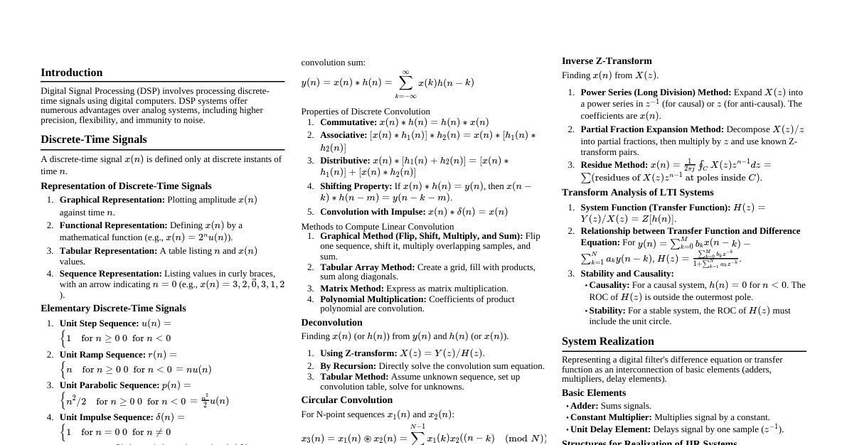
### Digital Communication Systems Digital communication is the process of devices communicating information digitally. #### Advantages of Digital Communication - Withstands channel noise and distortion better than analog communication. - Regenerative repeaters prevent noise accumulation. - Flexible digital hardware implementation. - Digital signals can be coded for low error rates, high fidelity, and privacy. - Easier and more efficient multiplexing of digital signals. - Digital storage is easy and inexpensive. - Reproduction of digital messages is extremely reliable. - Cost of digital hardware decreases while performance/capacity doubles over time. #### Block Diagram of Digital Communication System 1. **Information Source and Input Transducer:** Converts analog or digital information into a digital signal (1s and 0s). 2. **Source Encoder (Data Compression):** Efficiently converts source output into a sequence of binary digits. 3. **Channel Encoder:** Introduces redundancy into the binary sequence to overcome noise and interference. 4. **Digital Modulator:** Converts binary sequences into electrical signals for transmission. 5. **Channel:** Physical medium for signal transmission (e.g., coaxial cable, fiber optic). 6. **Digital Demodulator:** Restores data bits from the digitally modulated signal. 7. **Channel Decoder:** Reconstructs the original information sequence using the coding scheme. 8. **Source Decoder:** Decodes the sequence to create an approximate replica of the input at the transmitter end. 9. **Output Transducer:** Provides the desired signal in analog or digital format. ### Pulse Code Modulation (PCM) Basics PCM produces a series of numbers or digits representing the approximate amplitude of a signal sample at that instant. The message signal is represented by a sequence of coded pulses, achieving discrete representation in both time and amplitude. #### Basic Elements of PCM **Transmitter Section:** - **Sampling:** Measures the instantaneous value of an analog signal at regular intervals. The sampling rate ($f_s = 1/T_s$) must be greater than twice the highest frequency component of the message signal to prevent aliasing. - **Ideal/Impulse Sampling:** An impulse at each sampling instant. Not practical. - **Natural Sampling:** A pulse of short width with varying amplitude. - **Flat-Top Sampling:** Uses sample and hold with single amplitude value. Prone to Aperture effect (attenuation of high frequency components). - **Quantization:** Represents sampled amplitude values by a finite set of levels, converting a continuous-amplitude sample into a discrete-time signal. - **Quantization Error:** Difference between original analog signal and its quantized representation. Occurs because the original signal may not exactly match available levels. - **Uniform Quantization:** Quantization levels are uniformly spaced. - **Mid-Rise:** Origin in middle of rising part of staircase; even number of quantization levels. - **Mid-Tread:** Origin in middle of tread of staircase; odd number of quantization levels. - **Non-uniform Quantization:** Quantization levels are unequal, often logarithmic. Step size decreases for weak signals and increases for strong signals for better SNR. - **Encoding:** Converts each quantized level into a binary code. **Receiver Section:** - **Regeneration of Impaired Signals:** Increases signal strength and reconstructs the signal. - **Decoding:** Decodes the pulse-coded waveform to reproduce the original signal. - **Reconstruction Filter:** A low-pass filter used to get back the original signal after digital-to-analog conversion. #### Bandwidth Requirements of PCM Bandwidth for PCM signal = $n \cdot f_m$ Where, $n$ = No. of bits in PCM code, $f_m$ = signal bandwidth. #### Quantization Noise in PCM Quantization noise is introduced in the transmitter and can be made negligibly small with adequate representation levels and companding. - Total voltage range: $-V_{max}$ to $V_{max}$ - Number of quantized levels: $L = 2^n$ (where $n$ is number of bits for encoding a sample) - Step size: $\Delta = 2V_{max}/L$ - Maximum quantization error: $(-\Delta/2)$ to $(\Delta/2)$ - Average power of quantization error: $\Delta^2/12$ #### Companding in PCM A non-linear technique (combination of compressing and expanding) used in PCM to improve SNR for weak signals. - **Compression:** Done at the transmitter before quantization. - **Expansion:** Done at the receiver to restore the original signal. **Types of Companding:** - **A-law Companding:** Used for PCM telephone systems. Uniform quantization at $A=1$ (linear characteristic). Mid-rise at the origin. - **μ-law Companding:** Used for speech and music signals. Uniform quantization at $\mu=0$ (linear characteristic). Mid-tread at the origin. ### Differential Pulse Code Modulation (DPCM) DPCM reduces redundancy in highly correlated samples by taking a predicted sampled value and summarizing it with the quantized values. This reduces the overall bit rate and the number of bits needed to transmit one sample. #### DPCM Transmitter Consists of a Quantizer and Predictor with two summer circuits. The current sample $x(nT_s)$ is compared with a predicted value $\hat{x}(nT_s)$ to generate an error signal $e(nT_s)$. This error is quantized to $e_q(nT_s)$ and encoded. The predicted value is based on past samples. #### DPCM Receiver Consists of a decoder, a predictor, and a summer circuit. The decoder reconstructs the quantized error signal. This error and the predicted value are summed to produce the quantized version of the original signal. #### Advantages of DPCM - Lower bandwidth requirement compared to PCM. - Reduced quantization error due to the prediction filter. - Fewer bits required to represent one sample value compared to PCM. ### Delta Modulation (DM) DM transmits only one bit per sample, overcoming the large signaling rate and transmission channel bandwidth of PCM. It compares the present sample value with the previous sample and sends an indication of whether the amplitude increased or decreased. #### Operating Principle of DM - The input signal is approximated by a step signal. - The step size ($\Delta$) is fixed. - If the difference between the present sample and previous sample is positive, the approximated signal increases by $+\Delta$, and '1' is transmitted. - If the difference is negative, the approximated signal decreases by $-\Delta$, and '0' is transmitted. - Only one binary bit is transmitted per sample. #### DM Transmitter and Receiver The transmitter uses an accumulator to add the quantizer output ($\pm \delta$) to the previous sample approximation. The receiver reconstructs the signal using an accumulator and a low-pass filter. #### Noise in Delta Modulation - **Slope Overload Distortion (Startup Error):** Occurs when the input signal's rate of rise is too high for the fixed step size to follow. The staircase signal cannot approximate the steep segments of the input signal. - **Granular Noise:** Occurs when the step size is too large for small variations in the input signal, causing the staircase signal to oscillate around the input signal when it's relatively flat. #### Adaptive Delta Modulation (ADM) ADM modifies DM to overcome slope overload and granular noise by making the step size adaptive to variations in the input signal. - Step size increases for steep segments of $x(t)$. - Step size decreases for slowly varying segments of $x(t)$. ### Digital Modulation Schemes Digital modulation is the process of encoding binary data (1s and 0s) into the amplitude, phase, or frequency of a transmitted analog signal. #### Advantages of Digital Modulation - Higher information capacity. - Enhanced data security. - Quicker system availability. - Better quality communication. - Conveys larger amounts of data than analog schemes. #### Types of Digital Modulation Techniques - Amplitude-Shift Keying (ASK) - Frequency-Shift Keying (FSK) - Phase-Shift Keying (PSK) #### Amplitude Shift Keying (ASK) ASK represents binary data by varying the amplitude of a signal. - Bit 1: Represented by high amplitude. - Bit 0: Represented by low or zero amplitude. **Generation of ASK:** The input binary sequence modulates a sinusoidal carrier. A product modulator/mixer passes the carrier when the input bit is '1' and blocks it when the input bit is '0'. **Reception of ASK:** Two types of receivers: 1. **Coherent/Synchronous ASK Receiver:** Requires a replica carrier wave of the same frequency and phase at the receiver for comparison. 2. **Non-Coherent/Asynchronous ASK Receiver:** Does not require a replica carrier wave. Simpler but has worse performance. #### Binary Frequency Shift Keying (BFSK) BFSK shifts the frequency of the carrier signal according to binary symbols (1, 0), while phase and amplitude remain unaffected. - Binary symbols (1, 0) modulate the carrier frequency. **FSK Modulator/Generator:** Comprises two oscillators (for high and low frequencies) connected to a switch with an internal clock to avoid abrupt phase discontinuities. The binary input sequence selects the appropriate frequency. **FSK Demodulator/Receptor:** Two types of demodulators: 1. **Asynchronous FSK Detector:** Uses two Band Pass Filters (BPFs) tuned to "Space" (0s) and "Mark" (1s) frequencies. Outputs are fed to envelope detectors, and a decision circuit selects the output with more power. 2. **Synchronous FSK Demodulator:** Uses two mixers with local oscillators and band-pass filters, acting as demodulators. A decision circuit selects the most likely output. #### Binary Phase Shift Keying (BPSK) Also known as 2-phase PSK or Phase Reversal Keying. The sine wave carrier undergoes phase reversals (0° and 180°) to represent binary data. It's a Double Side Band Suppressed Carrier modulation scheme. **BPSK Modulator:** Uses an inverter circuit to achieve a 180° phase shift. When binary data is '1', a sine wave is output. When binary data is '0', the sine wave is inverted (180° phase shift). **BPSK Demodulator:** - **Coherent Carrier Recovery:** Detects and regenerates a carrier signal coherent with the original. - **Balanced Modulator:** Product of input and recovered carrier. In-phase waves produce positive DC voltage; out-of-phase waves produce negative DC voltage. - **LPF:** Passes only the DC component. - **Clock Recovery & Level Converter:** Produces perfect high/low voltages for logic 1 (positive) and logic 0 (negative). #### Quaternary Phase Shift Keying (QPSK) An expanded version of BPSK where a symbol consists of two bits (a "dibit"), allowing for four possible dibits. Each symbol carries the same energy. - Converts digital bits into bit-pairs, which halves the data bit rate. - For a given binary data rate, the transmission bandwidth for QPSK is half of that needed by BPSK. #### Differential Phase Shift Keying (DPSK) In DPSK, the phase of the modulated signal is shifted relative to the previous signal element, eliminating the need for a reference signal. The signal phase follows the high or low state of the previous element. - If the data bit is LOW (0), the phase does not reverse. - If the data bit is HIGH (1), the phase reverses (inverts). - Multiple bits can be transmitted at a time, reducing channel bandwidth. #### Comparison of Digital Modulation Schemes | Parameter | ASK | FSK | PSK | |--------------------|-----------------------------------|-------------------------------------|---------------------------------------| | Variable Characteristic | Amplitude | Frequency | Phase | | Noise Immunity | Low | High | High | | Complexity | Simple | Moderate | Very Complex | | Error Probability | High | Low | Low | | Performance in Presence of Noise | Poor | Better than ASK | Better than FSK | | Bit Rate | Suitable up to 100 bits per sec | Suitable up to 1200 bits per sec | Suitable for higher bit rate | | Bandwidth | 2Rb | 2Rb + ($F_2-F_1$) | 2Rb | | | Rb-bit rate | $F_2$-higher frequency for bit 1 in FSK | $F_1$-lower frequency for bit 0 in FSK | ### Spread Spectrum Communication Spread Spectrum Modulation is a technique where the transmitted sequence occupies much more bandwidth than the minimum required bandwidth. #### Characteristics - Increased bandwidth usage for the sequence passing through the channel. - Provides better security. - Involves spectrum spreading at the transmitter and dispreading at the receiver. - Spreading is achieved by converting a single input bit into multiple bits, increasing frequency and bandwidth. - Uses a Pseudo-Noise (PN) sequence generator for spreading. #### Pseudo Noise (PN) Sequence Generator A PN sequence is a deterministic sequence of binary values that appears random but is generated by a deterministic algorithm. - If the algorithm and initial conditions are known, the sequence can be reproduced. - PN sequences are designed with a specific period or cycle length. ### Frequency-Hop Spread Spectrum (FHSS) FHSS is an analog spread spectrum technique. #### Block Diagram #### Principle - The original input sequence is first FSK modulated. - The FSK modulated signal is then passed to a mixer/spreader. - The spreader mixes the FSK modulated signal with a frequency from a frequency synthesizer to produce the spread spectrum signal. - A PN generator generates a particular code at an instant, and according to this code, a carrier frequency is selected by the frequency synthesizer. - **Frequency Hopping:** The process of changing frequency with respect to time. #### Applications of FHSS - Bluetooth (1600 frequency hops per second). - JTRS (Joint Tactical Radio System). ### Direct Sequence Spread Spectrum (DSSS) DSSS is a digital spread spectrum technique that extends the bandwidth of the input signal. #### Characteristics - Extends the bandwidth of the input signal. - Input signal can be modulated by PSK/QPSK/QAM. - Used for increasing bit error rate (BER) and bandwidth efficiency. - Chip generator uses Barker codes to generate codes, with output in terms of +1 or -1. #### DSSS Waveform #### Advantages of DSSS - Better security than FHSS. - Improved immunity against jamming. #### Applications of DSSS - CDMA (2G and 3G). ### Multiple Access Techniques Multiple access techniques enable multiple users to share a common communication channel without interference. #### Common Techniques - Frequency Division Multiple Access (FDMA) - Time Division Multiple Access (TDMA) - Code Division Multiple Access (CDMA) #### Frequency Division Multiple Access (FDMA) A multiple access technique that divides the available frequency spectrum into multiple non-overlapping subchannels or frequency slots. **Features:** - Each FDMA channel carries only one phone circuit at a time. - FDMA channels are idle when not in use. - Provides relatively narrow channels (e.g., 30 KHz). - Requires tight RF filtering to avoid near-channel interference. - FDMA mobile units use a duplexer for frequency separation, increasing cost. - Total number of channels: $N = \frac{B_t - 2B_{guard}}{B_c}$ - $B_t$: total spectrum - $B_{guard}$: guard band - $B_c$: channel bandwidth **Advantages:** - Minimizes interference as users operate on separate frequency bands. - Relatively simple to implement and manage. - Constant frequency allocation during communication ensures predictable access. **Applications:** - Point-to-point microwave links. - Older analog cellular networks. #### Time Division Multiple Access (TDMA) A multiple access technique that allows multiple users to share the same communication channel by allocating specific time slots. **Features:** - Commonly used in digital communication systems. - Each time slot represents a portion of time for a user to transmit or receive data using the entire bandwidth. - Transmits data in a buffer and burst method, requiring digital data and modulation. - Easy handoff (mobile unit checks power level from neighboring base stations during idle time slots). - High synchronization overhead due to buffer and burst method. - Guard slots are necessary to separate users. - On-demand supply makes the system efficient. - Max number of users ($m$) on each channel: $N = \frac{B_t - 2B_{guard}}{B_c}$ **TDMA Frame:** - Preamble and trail bits are used for synchronization. - Information messages are divided into multiple slots, each with trail, synchronization, and guard bits. - Guard bits prevent data overlapping due to transmission delays. **Advantages:** - Efficiently utilizes available channel bandwidth. - Predictable access as users are allocated specific time slots. - Minimal interference as users transmit at different times. **Applications:** - Older cellular networks (like 2G). - Some satellite communication. #### Code Division Multiple Access (CDMA) A digital wireless communication technology that allows multiple users to share the same frequency band simultaneously. **Features:** - Uses the entire time and frequency spectrum. - Each user is assigned a unique coding scheme (pseudo-random code or spreading sequence). - Codes are orthogonal, meaning they are independent and do not interfere with each other. - It is a spread spectrum communication. - Soft capacity limit (capacity can be increased by increasing the number of orthogonal codes). - Soft handoff (frequency does not change when moving between stations). - Near-far effect is avoided by power control (far away users transmit with high power, near users with less power). **Advantages:** - Efficient spectrum usage. - Robust against interference (noise suppressed using appropriate code). - Suitable for both small and large networks. **Applications:** - 2G and 3G cellular networks. **CDMA - Rake Receiver:** A specialized receiver used to recover transmitted signals from multipath environments. - "Rake" refers to collecting and combining multiple signal components from different paths to improve reception quality. - Handles signals arriving at different times and with different attenuations due to multipath. - Correlator circuits with different time delays extract information. - Weighted attenuators compensate for channel attenuation characteristics. ### Multicarrier Communication A technique where data is transmitted over multiple subcarriers within a broader frequency band. The available bandwidth is divided into several narrower, often orthogonal, subchannels. #### Orthogonal Space Subcarrier - Subcarriers are spaced to be orthogonal, preventing interference despite close spacing. - Maximizes spectral efficiency. - Reduces effects of fading and multipath interference (spatial diversity). - Provides higher SNR. - Simplifies signal processing at the receiver. #### Orthogonal Frequency Division Multiplexing (OFDM) A modulation technique where the frequency spectrum is divided into multiple orthogonal subcarriers. - Each subcarrier is modulated with a conventional scheme (QAM or PSK) at a low symbol rate. - Widely used in modern wireless communication (Wi-Fi, 4G LTE, 5G, digital TV). - System bandwidth is divided into parallel, overlapping, yet orthogonal sub-bands. - Data is split into independent streams, modulating different sub-carriers, then multiplexed. - OFDM is a special case of FDM. - Significantly improves spectral efficiency. - Avoids the need for steep band-pass filters and a bank of oscillators (can be digitally implemented). **FDM vs OFDM:** **OFDM Spectrum:** **Advantages of OFDM:** - Permits densely packed and overlapping sub-carriers. - Offers spectrally efficient transmission. - Can be digitally implemented (fast and efficient signal processing). - Flexible use of spectrum. - Supports different modulation schemes based on channel conditions. - Almost completely avoids the need for an equalizer. ### Information Theory Information theory deals with the mathematical modeling and analysis of a communication system. #### Information - **Definition:** Message is the physical manifestation of information produced by the source. Information is organized data with meaningful application for the receiver. - **Information Content:** Based on the idea that less probable events carry more information. - More unexpected events give more information. - Probability of an event is inversely related to its unexpectedness and information content. - If an event has probability $P$, its information content $I$ is directly proportional to $1/P$, i.e., $I = \log(1/P)$. - **Unit of Information:** A source emits one of $q$ possible messages $m_1, m_2, \dots, m_q$ with probabilities $p_1, p_2, \dots, p_q$. The information content of the $k$-th message is $I(m_k) = \log_2(1/p_k)$ bits. #### Entropy (H) The average amount of information per source symbol in a particular interval. - For a discrete memoryless source with alphabet $A = \{s_0, s_1, \dots, s_{M-1}\}$ and probabilities $p_0, p_1, \dots, p_{M-1}$, the entropy is given by: $$H = \sum_{i=0}^{M-1} p_i \log_2 \left(\frac{1}{p_i}\right) \text{ bits/symbol}$$ - Entropy attains its maximum value when symbol probabilities are equal. #### Shannon-Hartley Theorem This theorem states the maximum rate at which information can be transmitted over a communication channel of a specified bandwidth in the presence of noise. - Channel Capacity ($C$) = $B \log_2(1 + S/N)$ - $C$: Channel capacity (bits/second) - $B$: Bandwidth (Hz) - $S/N$: Signal-to-noise ratio #### Coding The process of converting digital data into a specific format for transmission, reception, and accurate decoding. **Need for Coding:** 1. Error Detection and Correction 2. Efficiency in Bandwidth Usage 3. Robustness to Channel Distortions 4. Security and Privacy 5. Compatibility and Interoperability 6. Capacity Enhancement 7. Adaptability to Channel Conditions #### Shannon-Fano Algorithm A data compression technique that assigns variable-length codes to symbols based on their probabilities of occurrence. More probable symbols get shorter codes. **Working Principle:** 1. Calculate probabilities of occurrence for each symbol. 2. Sort symbols in descending order of probabilities. 3. Divide symbols into two subsets with approximately equal probability sums. 4. Assign '0' to symbols in the first subset and '1' to symbols in the second. 5. Repeat steps 3 and 4 for each subset until all symbols are coded. 6. Encode data by replacing symbols with their codes. **Example Table:** | X | P(X) | Steps | Code | |---|------|-----------|---------| | E | 0.4 | 0 | 0 | | A | 0.3 | 10 | 10 | | D | 0.15 | 110 | 110 | | B | 0.1 | 1110 | 1110 | | F | 0.03 | 11110 | 11110 | | C | 0.02 | 11111 | 11111 | #### Error Detection and Correction Codes Used to detect and correct errors (bit changes from 0 to 1 or vice versa) in digital communication. **Types of Codes:** - **Error Detection Codes:** Detect errors (e.g., Parity Code, Hamming Code). - **Error Correction Codes:** Find the number and positions of corrupted bits. **Parity Bit Method:** Adds extra redundant bits to actual data to detect errors. - **Even Parity:** Total number of '1's in the message (including parity bit) is even. - **Odd Parity:** Total number of '1's in the message (including parity bit) is odd. | Message | Odd Parity | Even Parity | |---------|------------|-------------| | 000 | 1 | 0 | | 001 | 0 | 1 | | 010 | 0 | 1 | | 011 | 1 | 0 | | 100 | 0 | 1 | | 101 | 1 | 0 | | 110 | 1 | 0 | | 111 | 0 | 1 | **Hamming Code:** A block code that divides messages into fixed-sized blocks and adds redundant bits for error detection and correction. - Represented as $(n, k)$ code, where $n$ is total bits, $k$ is message bits, and $r = n-k$ is parity bits. - Condition for parity bits: $2^r \ge k + r + 1$. - Redundant bits are placed at positions corresponding to powers of 2 (1, 2, 4, 8, ...). - Each data bit is included in a unique set of parity bits. **Determining Position of Redundant Bits:** - Parity bit 1 covers positions whose binary representation includes '1' in LSB (1, 3, 5, 7, 9, 11...). - Parity bit 2 covers positions whose binary representation includes '1' in 2nd position from LSB (2, 3, 6, 7, 10, 11, 15...). - Parity bit 4 covers positions whose binary representation includes '1' in 3rd position from LSB (4, 5, 6, 7, 12, 13, 14, 15...). - Parity bit 8 covers positions whose binary representation includes '1' in 4th position from LSB (8, 9, 10, 11, 12, 13, 14, 15...). **Linear Block Codes:** A block code is linear if the sum of any two code words gives another code word ($C_p = C_i + C_k$). - Used for error-correcting in digital communication. - Properties: Linearity, Error Detection and Correction, Generator and Parity-Check Matrices, Error Correction Algorithms. - Code rate: Ratio of information bits ($k$) to total bits ($n$). Higher code rate means higher efficiency.