Hibbeler
Cheatsheet Content
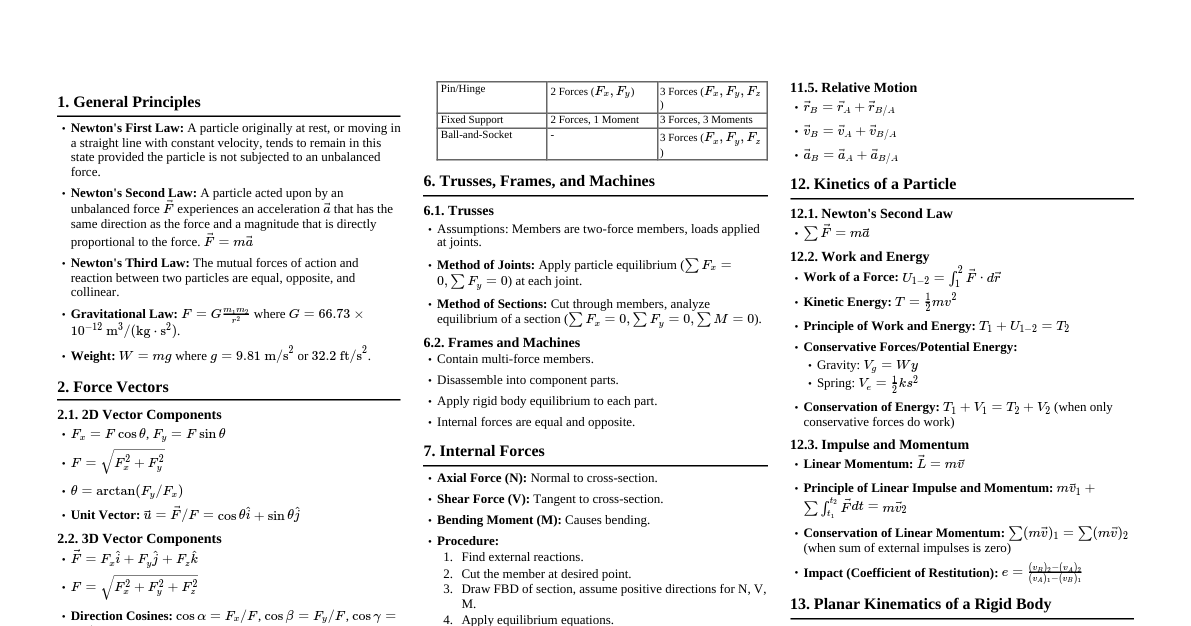
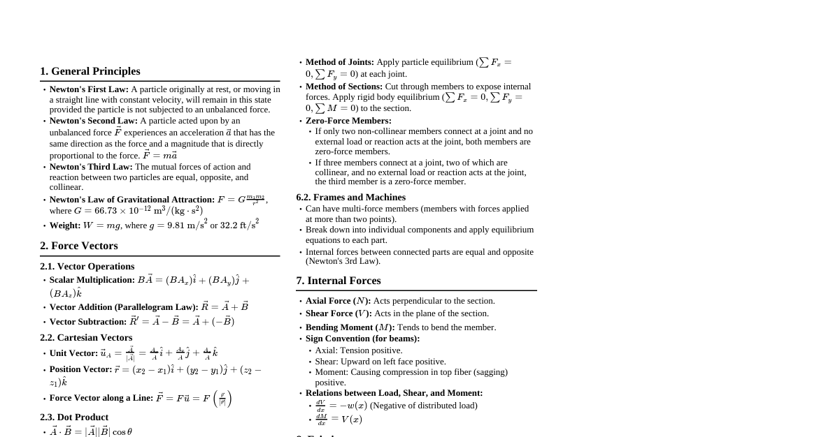
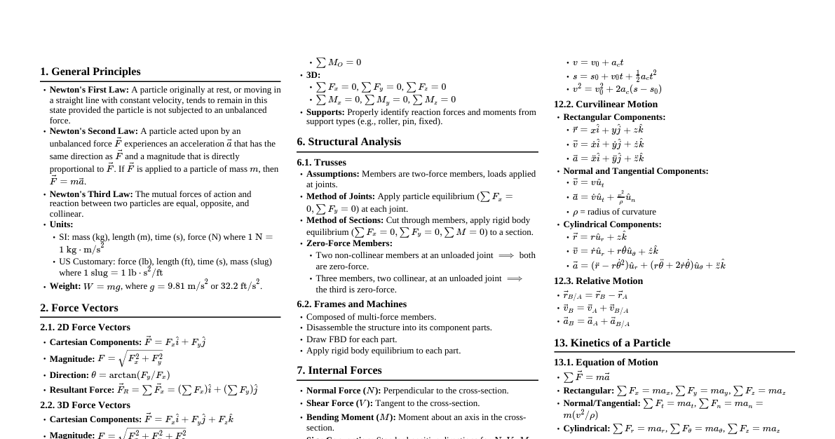
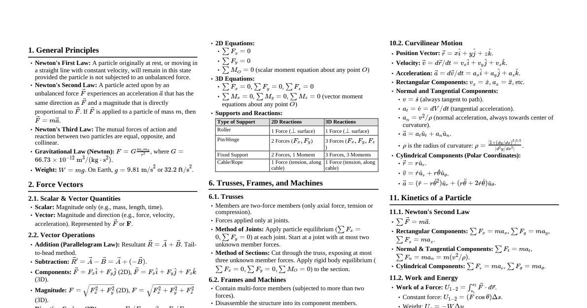
1. General Principles Newton's First Law: A particle originally at rest, or moving in a straight line with constant velocity, will remain in this state provided the particle is not subjected to an unbalanced force. Newton's Second Law: A particle acted upon by an unbalanced force $\vec{F}$ experiences an acceleration $\vec{a}$ that has the same direction as the force and a magnitude that is directly proportional to the force. $ \vec{F} = m\vec{a} $ Newton's Third Law: The mutual forces of action and reaction between two particles are equal, opposite, and collinear. Newton's Law of Gravitational Attraction: $ F = G \frac{m_1 m_2}{r^2} $ $G = 6.673 \times 10^{-11} \text{ m}^3/(\text{kg} \cdot \text{s}^2)$ (Universal Gravitational Constant) Weight: $ W = mg $ $g = 9.81 \text{ m/s}^2$ or $32.2 \text{ ft/s}^2$ (Acceleration due to gravity) Scalars: Mass, Volume, Length, Time (only magnitude) Vectors: Force, Velocity, Position (magnitude and direction) 2. Force Vectors 2.1 2D Vector Operations Cartesian Vector Form: $ \vec{F} = F_x \hat{i} + F_y \hat{j} $ Magnitude: $ F = \sqrt{F_x^2 + F_y^2} $ Direction: $ \theta = \tan^{-1}\left(\frac{F_y}{F_x}\right) $ Resultant Force: $ \vec{F}_R = \sum \vec{F}_x \hat{i} + \sum \vec{F}_y \hat{j} $ 2.2 3D Vector Operations Cartesian Vector Form: $ \vec{F} = F_x \hat{i} + F_y \hat{j} + F_z \hat{k} $ Magnitude: $ F = \sqrt{F_x^2 + F_y^2 + F_z^2} $ Direction Cosines: $ \cos\alpha = \frac{F_x}{F} $ $ \cos\beta = \frac{F_y}{F} $ $ \cos\gamma = \frac{F_z}{F} $ $ \cos^2\alpha + \cos^2\beta + \cos^2\gamma = 1 $ Unit Vector: $ \vec{u}_F = \frac{\vec{F}}{F} = \cos\alpha \hat{i} + \cos\beta \hat{j} + \cos\gamma \hat{k} $ Position Vector (from A to B): $ \vec{r}_{AB} = (x_B - x_A)\hat{i} + (y_B - y_A)\hat{j} + (z_B - z_A)\hat{k} $ Force vector along a line: $ \vec{F} = F \vec{u}_{AB} = F \left( \frac{\vec{r}_{AB}}{r_{AB}} \right) $ 2.3 Dot Product $ \vec{A} \cdot \vec{B} = AB \cos\theta $ $ \vec{A} \cdot \vec{B} = A_x B_x + A_y B_y + A_z B_z $ Angle between two vectors: $ \theta = \cos^{-1}\left(\frac{\vec{A} \cdot \vec{B}}{AB}\right) $ Projection of $\vec{A}$ onto $\vec{B}$: $ A_B = \vec{A} \cdot \vec{u}_B $ 3. Equilibrium of a Particle Free-Body Diagram (FBD): Essential for solving equilibrium problems. Isolates the particle and shows all external forces acting on it. Conditions for Equilibrium: 2D: $ \sum F_x = 0 $, $ \sum F_y = 0 $ 3D: $ \sum F_x = 0 $, $ \sum F_y = 0 $, $ \sum F_z = 0 $ Spring Force: $ F = ks $ (Hooke's Law) $k$ is the spring stiffness, $s$ is the deformation (stretch or compression). 4. Force System Resultants 4.1 Moment of a Force (Scalar Formulation, 2D) $ M_O = Fd $ (Force $\times$ perpendicular distance) Positive for counter-clockwise rotation, negative for clockwise. 4.2 Moment of a Force (Vector Formulation, 3D) $ \vec{M}_O = \vec{r} \times \vec{F} $ $\vec{r}$ is position vector from point $O$ to any point on the line of action of $\vec{F}$. Cross Product: $$ \vec{A} \times \vec{B} = \begin{vmatrix} \hat{i} & \hat{j} & \hat{k} \\ A_x & A_y & A_z \\ B_x & B_y & B_z \end{vmatrix} $$ Magnitude of Cross Product: $ |\vec{A} \times \vec{B}| = AB \sin\theta $ 4.3 Principle of Moments (Varignon's Theorem) The moment of a force about a point is equal to the sum of the moments of the force's components about the point. $ \vec{M}_O = \vec{r} \times \vec{F} = \vec{r} \times (\vec{F}_x + \vec{F}_y + \vec{F}_z) = (\vec{r} \times \vec{F}_x) + (\vec{r} \times \vec{F}_y) + (\vec{r} \times \vec{F}_z) $ 4.4 Moment of a Couple A couple consists of two parallel forces that are equal in magnitude, opposite in direction, and separated by a perpendicular distance $d$. Magnitude: $ M = Fd $ (independent of the point of moment calculation) Vector: $ \vec{M} = \vec{r} \times \vec{F} $ 4.5 Equivalent Systems A force system can be reduced to a single resultant force $\vec{F}_R$ acting at a point $O$ and a resultant couple moment $\vec{M}_{R_O}$. $ \vec{F}_R = \sum \vec{F} $ $ \vec{M}_{R_O} = \sum \vec{M}_O + \sum \vec{M}_{couple} $ Wrench: A force-couple system where the force and moment are collinear. 5. Equilibrium of a Rigid Body 5.1 Conditions for Rigid Body Equilibrium 2D (Coplanar Force System): $ \sum F_x = 0 $ $ \sum F_y = 0 $ $ \sum M_O = 0 $ (Moment summation about any point O) 3D: $ \sum \vec{F} = 0 \implies \sum F_x = 0, \sum F_y = 0, \sum F_z = 0 $ $ \sum \vec{M}_O = 0 \implies \sum M_x = 0, \sum M_y = 0, \sum M_z = 0 $ 5.2 Supports and Reactions Support Type 2D Reactions 3D Reactions Roller 1 normal force 1 normal force Pin/Hinge 2 force components 3 force components Fixed Support 2 force components, 1 moment 3 force components, 3 moments Cable/Rope 1 tension force (along cable) 1 tension force (along cable) Smooth Surface 1 normal force 1 normal force 5.3 Two-Force and Three-Force Members Two-Force Member: A member subjected to forces at only two points. The forces must be equal, opposite, and collinear along the line connecting the two points. Three-Force Member: A member subjected to forces at three points. If in equilibrium, the lines of action of the three forces must be concurrent or all parallel. 6. Trusses, Frames, and Machines 6.1 Trusses Composed of slender members joined at their ends. All members are two-force members (only axial force, tension or compression). Assumptions: Members are joined by smooth pins. Loads are applied at the joints. Method of Joints: Apply particle equilibrium equations ($\sum F_x = 0, \sum F_y = 0$) to each joint. Start at a joint with at most two unknown member forces. Method of Sections: Cut the truss into two sections through members whose forces are to be determined (usually 3 unknown members). Apply rigid body equilibrium equations ($\sum F_x = 0, \sum F_y = 0, \sum M_O = 0$) to one section. Zero-Force Members: Identify members with no force to simplify analysis. If only two non-collinear members connect at a joint and no external load or support reaction is applied to the joint, then both members are zero-force members. If three members connect at a joint, two of which are collinear, and no external load or support reaction is applied to that joint, then the third member is a zero-force member. 6.2 Frames and Machines Structures with at least one multi-force member (member subjected to more than two forces). Used to support loads (frames) or transmit/alter forces (machines). Analysis: Draw FBD of the entire structure to find external reactions. Disassemble the structure into its individual members. Draw FBD for each member, showing all internal forces as equal and opposite pairs at connections. Apply rigid body equilibrium equations to each member (or combinations of members). 7. Internal Forces Axial Force (N): Perpendicular to the section, acting along the member's axis. Shear Force (V): Parallel to the section, tangential to the surface. Bending Moment (M): Causes rotation about an axis perpendicular to the member's axis. Sign Convention: Axial: Tension (+), Compression (-) Shear: Up on left face (+), Down on left face (-) Moment: Causes compression in top fibers (+) Procedure: Determine external reactions. Pass an imaginary section through the member. Draw FBD of either segment. Apply equilibrium equations to find $N, V, M$. Relations between Load, Shear, and Moment: $ \frac{dV}{dx} = -w(x) $ (Rate of change of shear = negative distributed load) $ \frac{dM}{dx} = V(x) $ (Rate of change of moment = shear force) 8. Friction Static Friction: $ F_s \le \mu_s N $ $F_s$: static friction force, $N$: normal force, $\mu_s$: coefficient of static friction. When impending motion: $ F_{s, max} = \mu_s N $ Kinetic Friction: $ F_k = \mu_k N $ $F_k$: kinetic friction force, $\mu_k$: coefficient of kinetic friction. Always $ \mu_k Angle of Static Friction: $ \phi_s = \tan^{-1}(\mu_s) $ Angle of Repose: The maximum angle of inclination of a surface at which a body will remain at rest due to friction. 9. Center of Gravity and Centroid Center of Gravity (CG): Point where the entire weight of a body appears to act. $ \bar{x} = \frac{\sum W_i x_i}{\sum W_i} $, $ \bar{y} = \frac{\sum W_i y_i}{\sum W_i} $, $ \bar{z} = \frac{\sum W_i z_i}{\sum W_i} $ Centroid: Geometric center of an area or volume. Area: $ \bar{x} = \frac{\sum \bar{x}_i A_i}{\sum A_i} $, $ \bar{y} = \frac{\sum \bar{y}_i A_i}{\sum A_i} $ Volume: $ \bar{x} = \frac{\sum \bar{x}_i V_i}{\sum V_i} $, etc. Theorems of Pappus and Guldinus: Area of Revolution: $ A = \theta \bar{r} L $ (where $\theta$ is angle of revolution in radians, $\bar{r}$ is centroid distance from axis, $L$ is arc length). For full revolution, $ A = 2\pi \bar{r} L $. Volume of Revolution: $ V = \theta \bar{r} A $ (where $A$ is area being revolved). For full revolution, $ V = 2\pi \bar{r} A $. 10. Moment of Inertia Area Moment of Inertia: Measure of an object's resistance to bending or deflection. $ I_x = \int y^2 dA $ $ I_y = \int x^2 dA $ $ J_O = I_x + I_y = \int r^2 dA $ (Polar Moment of Inertia) Parallel-Axis Theorem: For an area A and its centroidal moment of inertia $I_{\bar{x}}$, the moment of inertia about a parallel axis $x'$ at distance $d_y$ is: $ I_{x'} = I_{\bar{x}} + Ad_y^2 $ Similarly, $ I_{y'} = I_{\bar{y}} + Ad_x^2 $ For polar moment of inertia: $ J_P = J_C + Ad^2 $ Radius of Gyration: $ k = \sqrt{\frac{I}{A}} $ 11. Kinematics of a Particle 11.1 Rectilinear Kinematics Position: $s$ Velocity: $ v = \frac{ds}{dt} $ Acceleration: $ a = \frac{dv}{dt} = \frac{d^2s}{dt^2} $ Differential relation: $ a \, ds = v \, dv $ Constant Acceleration Formulas: $ v = v_0 + a_c t $ $ s = s_0 + v_0 t + \frac{1}{2} a_c t^2 $ $ v^2 = v_0^2 + 2 a_c (s - s_0) $ 11.2 Curvilinear Kinematics Position Vector: $ \vec{r} = x\hat{i} + y\hat{j} + z\hat{k} $ Velocity Vector: $ \vec{v} = \frac{d\vec{r}}{dt} = \dot{x}\hat{i} + \dot{y}\hat{j} + \dot{z}\hat{k} $ Acceleration Vector: $ \vec{a} = \frac{d\vec{v}}{dt} = \ddot{x}\hat{i} + \ddot{y}\hat{j} + \ddot{z}\hat{k} $ Normal and Tangential Components: $ a_t = \dot{v} $ (rate of change of speed) $ a_n = \frac{v^2}{\rho} $ (where $\rho$ is radius of curvature) $ a = \sqrt{a_t^2 + a_n^2} $ Cylindrical Components: $ \vec{v} = \dot{r}\hat{u}_r + r\dot{\theta}\hat{u}_\theta + \dot{z}\hat{k} $ $ \vec{a} = (\ddot{r} - r\dot{\theta}^2)\hat{u}_r + (r\ddot{\theta} + 2\dot{r}\dot{\theta})\hat{u}_\theta + \ddot{z}\hat{k} $ 12. Kinetics of a Particle 12.1 Newton's Second Law $ \sum \vec{F} = m\vec{a} $ Rectangular Components: $ \sum F_x = ma_x $, $ \sum F_y = ma_y $, $ \sum F_z = ma_z $ Normal and Tangential Components: $ \sum F_t = ma_t $, $ \sum F_n = ma_n = m\frac{v^2}{\rho} $ Cylindrical Components: $ \sum F_r = m(\ddot{r} - r\dot{\theta}^2) $, $ \sum F_\theta = m(r\ddot{\theta} + 2\dot{r}\dot{\theta}) $, $ \sum F_z = m\ddot{z} $ 12.2 Work and Energy Work of a Force: $ U_{1-2} = \int_{s_1}^{s_2} F \cos\theta \, ds $ For constant force: $ U_{1-2} = F_c \cos\theta (s_2 - s_1) $ For weight: $ U_{1-2} = -W \Delta y $ For spring: $ U_{1-2} = \frac{1}{2}ks_1^2 - \frac{1}{2}ks_2^2 $ Principle of Work and Energy: $ T_1 + U_{1-2} = T_2 $ Kinetic Energy: $ T = \frac{1}{2}mv^2 $ Conservation of Energy: $ T_1 + V_1 = T_2 + V_2 $ (When only conservative forces do work) Gravitational Potential Energy: $ V_g = Wy $ Elastic Potential Energy: $ V_e = \frac{1}{2}ks^2 $ 12.3 Impulse and Momentum Linear Impulse: $ \vec{I} = \int_{t_1}^{t_2} \vec{F} dt $ Linear Momentum: $ \vec{L} = m\vec{v} $ Principle of Linear Impulse and Momentum: $ m\vec{v}_1 + \sum \int_{t_1}^{t_2} \vec{F} dt = m\vec{v}_2 $ Conservation of Linear Momentum: $ \sum m_i (\vec{v}_i)_1 = \sum m_i (\vec{v}_i)_2 $ (When net external impulse is zero) Impact: Coefficient of Restitution: $ e = \frac{(v_B)_2 - (v_A)_2}{(v_A)_1 - (v_B)_1} $ $e=1$ for perfectly elastic, $e=0$ for perfectly plastic. 13. Planar Kinematics of a Rigid Body Translation: All particles have same velocity and acceleration. $ \vec{v}_B = \vec{v}_A $ $ \vec{a}_B = \vec{a}_A $ Rotation about a Fixed Axis: Angular Velocity: $ \omega = \frac{d\theta}{dt} $ Angular Acceleration: $ \alpha = \frac{d\omega}{dt} $ Relation: $ \alpha \, d\theta = \omega \, d\omega $ Tangential Velocity: $ v = \omega r $ Tangential Acceleration: $ a_t = \alpha r $ Normal Acceleration: $ a_n = \omega^2 r = v^2/r $ Absolute General Plane Motion Analysis: Relates position, velocity, and acceleration of points on a rigid body using fixed coordinates. Relative Motion Analysis (Velocity): $ \vec{v}_B = \vec{v}_A + \vec{v}_{B/A} $ $ \vec{v}_{B/A} = \vec{\omega} \times \vec{r}_{B/A} $ Relative Motion Analysis (Acceleration): $ \vec{a}_B = \vec{a}_A + \vec{a}_{B/A} $ $ \vec{a}_{B/A} = \vec{\alpha} \times \vec{r}_{B/A} - \omega^2 \vec{r}_{B/A} $ Instantaneous Center of Zero Velocity (IC): A point on the body (or its extension) that has zero velocity at a given instant. Useful for velocity analysis. 14. Planar Kinetics of a Rigid Body Equations of Motion: $ \sum F_x = m(\bar{a}_x) $ $ \sum F_y = m(\bar{a}_y) $ $ \sum M_G = I_G \alpha $ (Moment about center of mass G) Alternatively, $ \sum M_P = \sum (\mathcal{M}_k)_P $ (Moment about any point P) Mass Moment of Inertia: $ I = \int r^2 dm $ Parallel-Axis Theorem: $ I = I_G + md^2 $ 14.1 Work and Energy Kinetic Energy: $ T = \frac{1}{2}m v_G^2 + \frac{1}{2} I_G \omega^2 $ Principle of Work and Energy: $ T_1 + U_{1-2} = T_2 $ 14.2 Impulse and Momentum Linear Impulse and Momentum: $ m(\vec{v}_G)_1 + \sum \int_{t_1}^{t_2} \vec{F} dt = m(\vec{v}_G)_2 $ Angular Impulse and Momentum: $ (H_G)_1 + \sum \int_{t_1}^{t_2} M_G dt = (H_G)_2 $ Angular Momentum: $ H_G = I_G \omega $