Mechanical Meas. & Metrology
Cheatsheet Content
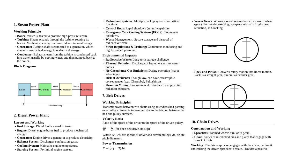
### Measurement System Basics #### Generalized Measurement System A generalized measurement system typically consists of: 1. **Primary Sensing Element:** Detects the physical variable. 2. **Variable Conversion Element:** Converts the sensed variable into a more suitable form (e.g., electrical signal). 3. **Variable Manipulation Element:** Modifies the signal to improve its quality or prepare it for further processing. 4. **Data Transmission Element:** Transmits the signal to the next stage. 5. **Data Presentation Element:** Displays or records the measured value. #### Definitions - **Threshold:** The minimum input that produces a detectable output change. - **Linearity:** The maximum deviation of the calibration curve from a specified straight line. - **Drift:** The change in output over a period of time for a constant input. - **Resolution:** The smallest change in the input that the instrument can detect and accurately indicate. - **Accuracy:** The closeness of the measured value to the true value. - **Range:** The set of input values for which an instrument is designed. - **Span:** The algebraic difference between the upper and lower limits of the range. - **Fidelity:** The ability of a system to reproduce the input signal without dynamic error. - **Dead Time:** The time delay from when a change in input occurs until the system begins to respond. - **Dead Zone:** The largest change in input quantity for which there is no output of the instrument. - **Overshoot:** The amount by which a system's response exceeds the final steady-state value. #### Errors in Measurement - **Gross Errors:** Human mistakes (e.g., misreading, incorrect application). - **Systematic Errors:** Consistent and repeatable errors, often due to instrument defects, environmental conditions, or observational errors. - **Instrumental Errors:** Due to faulty construction, calibration, or loading effects. - **Environmental Errors:** Due to external conditions like temperature, pressure, humidity. - **Observational Errors:** Due to habits of observer, e.g., parallax. - **Random Errors:** Unpredictable variations in observed readings, often due to unknown and uncontrollable causes. #### Error Correction Methods - **Calibration:** Comparing the instrument's output to a known standard. - **Compensation:** Using techniques to counteract known systematic errors (e.g., temperature compensation). - **Averaging:** Reducing random errors by taking multiple readings and averaging them. - **Careful Observation:** Minimizing gross and observational errors. ### Dynamic Characteristics & System Response #### Dynamic Characteristics These describe the instrument's behavior when the input is changing rapidly. - **Speed of Response:** How quickly the instrument responds to a change in input. - **Measuring Lag:** The delay in the instrument's response to an input change. - **Frequency Response:** How well the instrument responds to different frequencies of input signals. #### First Order System Response For a first-order system with transfer function $G(s) = \frac{K}{\tau s + 1}$, subjected to a unit step input $X(s) = \frac{1}{s}$, the output in Laplace domain is: $$Y(s) = G(s)X(s) = \frac{K}{s(\tau s + 1)}$$ Taking the inverse Laplace transform, the time domain response is: $$y(t) = K(1 - e^{-t/\tau})$$ Where $K$ is the steady-state gain and $\tau$ is the time constant. #### Second Order System Response A general second-order system transfer function is $G(s) = \frac{\omega_n^2}{s^2 + 2\zeta\omega_n s + \omega_n^2}$, where $\omega_n$ is the natural frequency and $\zeta$ is the damping ratio. For a sinusoidal input $x(t) = A \sin(\omega t)$, the steady-state response $y_{ss}(t)$ will also be sinusoidal with the same frequency $\omega$, but with a different amplitude and a phase lag. **Amplitude Ratio (AR)** and **Phase Lag ($\phi$)** for a second-order system: $$AR = \frac{1}{\sqrt{[1 - (\omega/\omega_n)^2]^2 + [2\zeta(\omega/\omega_n)]^2}}$$ $$\phi = \arctan\left(\frac{2\zeta(\omega/\omega_n)}{1 - (\omega/\omega_n)^2}\right)$$ The steady-state output is $y_{ss}(t) = A \cdot AR \cdot \sin(\omega t - \phi)$. **Example:** Given: $\omega_n = 100 \text{ Hz}$, $\zeta = 0.7$, input frequency $\omega = 40 \text{ Hz}$. $\omega/\omega_n = 40/100 = 0.4$ $AR = \frac{1}{\sqrt{[1 - (0.4)^2]^2 + [2 \cdot 0.7 \cdot 0.4]^2}} = \frac{1}{\sqrt{[1 - 0.16]^2 + [0.56]^2}} = \frac{1}{\sqrt{[0.84]^2 + [0.56]^2}} \approx 1.05$ $\phi = \arctan\left(\frac{0.56}{0.84}\right) \approx 33.69^\circ$ or $0.588 \text{ radians}$ **Frequency range for AR = 1.00 ± 0.01:** This requires solving for $\omega/\omega_n$ when $0.99 \le AR \le 1.01$. This is typically a band around the natural frequency, depending on the damping ratio. #### Noise in Measurement System Noise refers to unwanted signals that interfere with the measurement of the desired signal, leading to inaccuracies. - **Internal Noise:** Generated within the instrument itself (e.g., thermal noise in resistors). - **External Noise:** Originates from external sources (e.g., electromagnetic interference, vibrations). - **Methods to Reduce Noise:** Shielding, filtering, grounding, signal averaging, proper sensor selection. ### Temperature Measurement #### Liquid-in-Glass Tube Thermometer - **Principle:** Thermal expansion of a liquid (mercury or alcohol) confined in a glass bulb and capillary tube. - **Construction:** - **Bulb:** Contains the liquid, usually thin-walled for good thermal contact. - **Capillary Tube:** A narrow bore tube, allowing the liquid to rise. - **Scale:** Calibrated markings to read temperature. - **Stem:** The glass tube enclosing the capillary. - **Working:** As temperature increases, the liquid in the bulb expands more than the glass, causing it to rise in the capillary. The height corresponds to the temperature. #### Thermocouple - **Principle:** Seebeck effect – when two dissimilar metals are joined at two junctions and these junctions are held at different temperatures, a voltage (thermoelectric EMF) is generated. - **Construction:** Two wires of dissimilar metals (e.g., Type K: Chromel and Alumel) are joined at one end (measuring junction) and connected to a reference junction (often at a known temperature or compensated electronically). - **Working:** The temperature difference between the measuring junction and the reference junction creates a voltage, which can be measured and correlated to temperature using a lookup table or polynomial. - **Advantages:** Wide temperature range, robust, relatively fast response. #### Optical Pyrometer - **Principle:** Measures temperature by comparing the intensity of visible radiation emitted by a hot body to that of a calibrated lamp filament. - **Construction:** Consists of an optical system, a red filter, a calibrated lamp filament, an eyepiece, and a current measuring circuit. - **Working:** The observer looks through the eyepiece, aligning the pyrometer with the hot object. The current through the lamp filament is adjusted until the filament disappears against the background of the hot object (brightness matching). The current required is then converted to temperature using a calibration curve. Used for very high temperatures where contact methods are impractical. ### Pressure Measurement #### Bourdon's Pressure Gauge - **Principle:** Pressure deforms a flattened, curved tube (Bourdon tube), and this deformation is mechanically amplified to move a pointer. - **Construction:** - **Bourdon Tube:** A C-shaped or helical/spiral tube with an elliptical cross-section, closed at one end and open to pressure at the other. - **Linkage Mechanism:** Connects the free end of the Bourdon tube to the pointer. - **Quadrant and Pinion:** Gears that convert the small tip movement into a larger rotational movement of the pointer. - **Pointer and Scale:** Indicates the pressure reading. - **Working:** When pressure is applied, the Bourdon tube tends to straighten. This movement is transmitted via the linkage and gear mechanism to rotate the pointer over a calibrated scale, directly indicating the pressure. - **Generalized Measurement System Perspective:** - **Primary Sensing Element:** Bourdon tube (senses pressure, converts to displacement). - **Variable Conversion/Manipulation:** Linkage and gear mechanism (amplifies displacement). - **Data Presentation:** Pointer and scale (displays pressure). #### McLeod Gauge - **Principle:** Compresses a known volume of gas at unknown low pressure to a smaller volume at a measurable higher pressure, applying Boyle's Law ($P_1V_1 = P_2V_2$). - **Construction:** Consists of a main glass bulb, a capillary tube with a closed end, a reference capillary, and a mercury reservoir. - **Working:** The gauge is connected to the system whose low pressure is to be measured. Mercury is raised to trap a known volume of gas from the system into the main bulb and capillary. The mercury is further raised to compress this trapped gas into the closed capillary. The height difference between the mercury levels in the closed capillary and the reference capillary, along with the known volumes, allows calculation of the original low pressure. Used for vacuum measurements. #### Hydraulic Load Cell - **Principle:** Converts a force or weight into a hydraulic pressure signal. - **Construction:** Typically consists of a piston, cylinder, a diaphragm (sometimes), and an incompressible fluid. The cylinder is connected to a pressure gauge. - **Working:** When a load is applied to the piston, it creates pressure in the fluid contained within the cylinder. This pressure is then transmitted to a pressure gauge, which can be calibrated to display the applied force or weight. ### Dimensional Metrology #### Limits, Fits, and Tolerances - **Limits:** The maximum and minimum permissible sizes of a feature. - **Tolerance:** The total permissible variation in the size of a feature. It is the difference between the upper and lower limits. - **Fit:** The relationship between two mating parts (e.g., shaft and hole) with respect to their limits of size. - **Hole Basis System:** The hole size is kept constant, and the shaft size is varied to achieve different fits. - **Shaft Basis System:** The shaft size is kept constant, and the hole size is varied to achieve different fits. - **Inference Fit:** Occurs when the minimum size of the shaft is larger than the maximum size of the hole, resulting in a permanent assembly. #### GO-NOGO Gauges - **Purpose:** Used for rapid inspection of parts to determine if they are within specified tolerance limits. They do not measure the actual size, only whether it is acceptable. - **Design for 50 H7/f6 Fit (Example):** - **Hole (H7):** Basic size 50 mm. H7 tolerance means a specific tolerance band for the hole (e.g., +0.025 mm, 0 mm for a 50 H7 hole). - GO Gauge (for hole): Checks the Minimum Material Limit (MMC) of the hole (i.e., the smallest permissible hole diameter). - NOGO Gauge (for hole): Checks the Maximum Material Limit (LMC) of the hole (i.e., the largest permissible hole diameter). - **Shaft (f6):** Basic size 50 mm. f6 tolerance means a specific tolerance band for the shaft (e.g., -0.025 mm, -0.041 mm for a 50 f6 shaft). - GO Gauge (for shaft): Checks the Maximum Material Limit (MMC) of the shaft (i.e., the largest permissible shaft diameter). - NOGO Gauge (for shaft): Checks the Minimum Material Limit (LMC) of the shaft (i.e., the smallest permissible shaft diameter). - **Drawing:** Typically shown as plug gauges for holes and ring gauges for shafts, with GO and NOGO ends clearly marked. #### Johansson Mikrokator - **Principle:** A mechanical comparator that uses a twisted metal strip to amplify small linear displacements into large angular deflections of a pointer. - **Construction:** A stylus rests on the workpiece. Its vertical movement causes a lever to rotate. This lever is attached to one end of a twisted metal strip. The other end of the strip is fixed. A lightweight pointer is attached to the middle of the twisted strip. - **Working:** As the stylus moves, the twisted strip untwists or twists further, causing the pointer to rotate significantly across a scale. - **Functions:** High magnification, excellent repeatability, low measuring force, no friction. Used for precise comparison measurements. #### Dial Indicator (Dial Gauge) - **Construction:** A plunger, rack and pinion mechanism, and a calibrated dial with a pointer. - **Working:** The plunger moves linearly when it contacts a surface. This linear motion is converted into rotational motion of the pointer via the rack and pinion, indicating the displacement on the dial. - **Functions:** Measures small linear displacements, checks flatness, parallelism, runout, and serves as a comparator. #### Sigma Comparator - **Principle:** A mechanical comparator that uses a knife-edge and moving block mechanism to amplify small movements of a measuring stylus. - **Construction:** Consists of a measuring stylus, a knife-edge pivoted lever, a moving block, and a pointer. - **Working:** The stylus movement causes the knife-edge to pivot, which in turn moves the block. This motion is significantly amplified and transmitted to a pointer moving over a scale. Known for its robustness and accuracy. #### Vernier Caliper - **Construction:** Consists of a main scale, a sliding jaw with a vernier scale, and fixed jaws. - **Working:** Measures linear dimensions (external, internal, depth) by comparing the main scale reading with the coinciding mark on the vernier scale, providing a precise reading. ### Angular Measurement #### Clinometer - **Principle:** Measures angles of slope, elevation, or depression with respect to gravity. - **Construction:** Typically involves a graduated arc and a plumb line or a spirit level, or an electronic sensor. - **Working:** The instrument is placed on the surface whose angle is to be measured. The plumb line or spirit level indicates the vertical or horizontal reference, and the angle is read from the scale. Digital clinometers use accelerometers to determine the angle. #### Measurement of Angle using Sine Bar - **Principle:** Uses the trigonometric principle of sine to convert a linear measurement into an angular one. - **Construction:** A precision hardened and ground steel bar with two cylindrical rollers of equal diameter fixed at its ends. The distance between the centers of these rollers is precisely known (e.g., 100mm, 200mm). - **Working:** The sine bar is placed on a surface plate. One roller rests directly on the surface plate, while the other roller is raised using slip gauges to a height 'h'. The angle $\theta$ of the workpiece placed on the sine bar is given by $\sin\theta = h/L$, where $L$ is the center distance between the rollers. Used for precise angle setting and measurement. ### Other Instruments & Tools #### Stroboscope - **Principle:** Uses intermittent light flashes to make cyclically moving objects appear slow-moving or stationary. - **Working:** The flash rate is adjusted to synchronize with the frequency of the rotating or vibrating object. When the flash frequency matches the object's frequency (or a multiple/submultiple), the object appears stationary or moves slowly, allowing for visual inspection of speed or motion. - **Application:** Measuring rotational speed (RPM), observing vibrations, analyzing cyclic processes. #### Rope Brake Dynamometer - **Principle:** Measures the power output of an engine by converting mechanical energy into heat through friction. - **Construction:** Consists of ropes wound around the flywheel of an engine, with one end attached to a spring balance and the other end loaded with weights. - **Working:** The friction between the ropes and the flywheel creates a braking torque. The net braking force (difference between weight and spring balance reading) multiplied by the effective radius of the flywheel gives the braking torque. Engine power is then calculated from this torque and the engine's RPM. #### Tool Maker's Microscope - **Purpose:** A precision optical instrument used for highly accurate two-dimensional measurements of small components, threads, and profiles. - **Construction:** Features a measuring stage that can move accurately in X and Y directions, a microscope with crosshairs, and often goniometric eyepieces for angle measurement. - **Working:** The workpiece is placed on the stage, and its edges or features are aligned with the crosshairs. The stage is moved, and the displacement is measured using micrometer heads or digital readouts. #### Optical Comparators (Profile Projectors) - **Principle:** Projects a magnified silhouette of a workpiece onto a screen, allowing for visual inspection and measurement. - **Construction:** Light source, projection lens, measuring stage, and a translucent screen with a protractor and scales. - **Working:** The workpiece is placed on the measuring stage, and light shines past it, creating a shadow image that is magnified and projected onto the screen. Measurements can be taken directly from the magnified image using rules or digital readouts on the screen. Used for complex profiles, small parts, and thread forms. ### Process Planning #### Detailed Process Planning Sheet - **Purpose:** A document that outlines the step-by-step manufacturing operations required to produce a part, from raw material to finished product. - **Key Elements:** 1. **Part Information:** Part name, number, material, quantity. 2. **Raw Material Selection:** Type, form, dimensions of the starting material. 3. **Operation Sequence:** A logical list of manufacturing steps (e.g., cutting, drilling, milling, heat treatment, grinding, inspection). 4. **Machine/Tooling:** Specific machines, fixtures, cutting tools, and measuring instruments required for each operation. 5. **Process Parameters:** Cutting speeds, feed rates, depth of cut, cycle times. 6. **Inspection/Quality Control:** Points where inspection is needed and the methods to be used. 7. **Sketches/Diagrams:** Visual aids for complex operations. 8. **Time Estimates:** Standard times for each operation. #### Manufacturing Plan - A broader strategy for producing a product, encompassing: - Overall production flow. - Facility layout. - Resource allocation (labor, machines). - Quality assurance plan. - Cost estimation.