Network Analysis & Synthesis
Cheatsheet Content
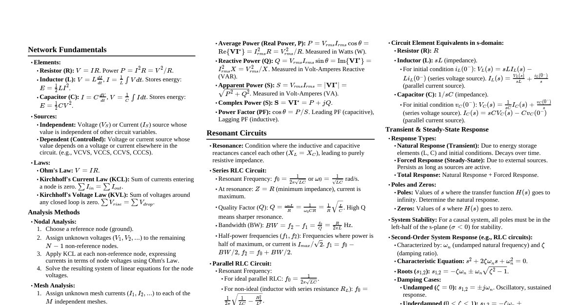
### LTI Elements & Transient Response - **LTI Elements:** Linear Time-Invariant elements (R, L, C). Their values don't change with time or signal amplitude. - **Behavior at t=0+ & t=∞:** - **Inductor (L):** - At `t=0+` (immediately after switching): Acts as an **open circuit** if current through it was zero before switching, or maintains its initial current if non-zero (current cannot change instantaneously). - At `t=∞` (steady state for DC): Acts as a **short circuit** (inductor voltage drops to zero as current becomes constant). - **Capacitor (C):** - At `t=0+`: Acts as a **short circuit** if voltage across it was zero before switching, or maintains its initial voltage if non-zero (voltage cannot change instantaneously). - At `t=∞` (steady state for DC): Acts as an **open circuit** (capacitor current drops to zero as voltage becomes constant). - **Time Concepts:** - `t=0-`: The instant just **before** a switching event. Used to determine initial conditions (e.g., $v_C(0-)$, $i_L(0-)$). - `t=0`: The exact instant of the switching event. - `t=0+`: The instant just **after** a switching event. Initial conditions determined at `t=0-` are valid here ($v_C(0+) = v_C(0-)$, $i_L(0+) = i_L(0-)$). - **Responses:** - **Zero Input Response (ZIR):** The response of a circuit when all independent sources are set to zero, and the response is solely due to the **initial energy stored** in capacitors and inductors. This describes the natural decay or oscillation of the circuit. - **Zero State Response (ZSR):** The response of a circuit when all initial conditions (stored energy) are set to zero, and the response is solely due to the **external input sources**. This describes how the circuit reacts to an applied signal. - **Complete Response:** The total response of a circuit, which is the sum of the Zero Input Response and the Zero State Response. - $Response_{complete} = Response_{ZIR} + Response_{ZSR}$ - **Transient Analysis of R-L, R-C, and R-L-C Circuits:** - **First-Order Circuits (R-C, R-L):** - Characterized by a single energy storage element. - The response is an exponential function: $f(t) = A + B e^{-t/\tau}$, where $\tau$ is the time constant. - For R-C: $\tau = RC$. For R-L: $\tau = L/R$. - Example (RC charging): $v_C(t) = V_S (1 - e^{-t/RC})$ - **Second-Order Circuits (R-L-C):** - Characterized by two energy storage elements (L and C). - The response is governed by a second-order differential equation. - The nature of the response (overdamped, critically damped, underdamped) depends on the damping factor ($\alpha$) and resonant frequency ($\omega_0$). - **Damping Factor ($\alpha$):** For series RLC, $\alpha = R/(2L)$. For parallel RLC, $\alpha = 1/(2RC)$. - **Resonant Frequency ($\omega_0$):** $\omega_0 = 1/\sqrt{LC}$. - **Damping Cases:** - **Overdamped ($\alpha > \omega_0$):** Two distinct real roots, slow exponential decay without oscillation. - **Critically Damped ($\alpha = \omega_0$):** Two identical real roots, fastest decay without oscillation. - **Underdamped ($\alpha ### Laplace Transform & Transfer Functions - **Laplace Transform (LT):** Converts time-domain functions $f(t)$ to s-domain functions $F(s)$. - $\mathcal{L}\{f(t)\} = F(s) = \int_0^\infty f(t)e^{-st} dt$ - **Poles:** Values of `s` for which $F(s)$ becomes infinite (roots of denominator). - **Zeros:** Values of `s` for which $F(s)$ becomes zero (roots of numerator). - **Transfer Function (H(s)):** Ratio of Laplace transform of output to Laplace transform of input, assuming zero initial conditions. - $H(s) = \frac{Y(s)}{X(s)}$ - **Circuit Analysis:** Use LT to convert differential equations into algebraic equations for easier solution for periodic and aperiodic excitations. ### Resonance & Coupled Circuits - **Series Resonance:** - Occurs when $X_L = X_C$, so $Z = R$. - Resonant frequency: $\omega_0 = \frac{1}{\sqrt{LC}}$ - **Q-factor:** $Q = \frac{\omega_0 L}{R} = \frac{1}{\omega_0 CR} = \frac{1}{R}\sqrt{\frac{L}{C}}$ - **Bandwidth (BW):** $BW = \frac{\omega_0}{Q} = \frac{R}{L}$ - **Selectivity:** Ability to distinguish between frequencies. Higher Q means higher selectivity. - **Parallel Resonance:** - Occurs when susceptances cancel. - Resonant frequency: $\omega_0 = \frac{1}{\sqrt{LC}}$ (for ideal parallel LC) - **Mutual Coupled Circuits:** - **Mutual Inductance (M):** $M = k\sqrt{L_1 L_2}$ where $k$ is coupling coefficient ($0 \le k \le 1$). - **Dot Convention:** Indicates phase relationship of induced voltages. Current entering dotted terminal induces positive voltage at dotted terminal of other coil. - **Equivalent Inductance:** - Series aiding: $L_{eq} = L_1 + L_2 + 2M$ - Series opposing: $L_{eq} = L_1 + L_2 - 2M$ ### Graph Theory - **Graph:** Consists of nodes (vertices) and branches (edges). - **Definitions:** - **Tree:** A subgraph connecting all nodes without forming any closed path. - **Co-tree:** Branches not in the tree. - **Twig:** A branch in the tree. - **Link:** A branch in the co-tree. - **Cut-set:** A set of branches whose removal divides the graph into two parts. - **Tie-set (Loop):** A closed path in the graph. - **Matrices:** - **Incidence Matrix (A):** Relates branches to nodes. - **Reduced Incidence Matrix ($A_r$):** Incidence matrix with one row removed (reference node). - **Fundamental Cut-set Matrix (B):** Relates cut-sets to branches. - **Fundamental Tie-set Matrix (C):** Relates loops to branches. ### Network Functions & Two-Port Networks - **Network Functions:** Ratio of output to input in the s-domain. - **Driving Point Impedance ($Z_{DP}(s)$):** $V(s)/I(s)$ at same port. - **Driving Point Admittance ($Y_{DP}(s)$):** $I(s)/V(s)$ at same port. - **Transfer Impedance ($Z_T(s)$):** $V_2(s)/I_1(s)$ (output voltage / input current). - **Transfer Admittance ($Y_T(s)$):** $I_2(s)/V_1(s)$ (output current / input voltage). - **Voltage Transfer Ratio ($G_V(s)$):** $V_2(s)/V_1(s)$. - **Current Transfer Ratio ($A_I(s)$):** $I_2(s)/I_1(s)$. - **Poles and Zeros:** Determine the frequency response and stability of the network. - **Two-Port Networks:** Characterized by two ports (input and output). - **Impedance (z) parameters:** $$ \begin{bmatrix} V_1 \\ V_2 \end{bmatrix} = \begin{bmatrix} z_{11} & z_{12} \\ z_{21} & z_{22} \end{bmatrix} \begin{bmatrix} I_1 \\ I_2 \end{bmatrix} $$ - **Admittance (y) parameters:** $$ \begin{bmatrix} I_1 \\ I_2 \end{bmatrix} = \begin{bmatrix} y_{11} & y_{12} \\ y_{21} & y_{22} \end{bmatrix} \begin{bmatrix} V_1 \\ V_2 \end{bmatrix} $$ - **Transmission (ABCD) parameters:** $$ \begin{bmatrix} V_1 \\ I_1 \end{bmatrix} = \begin{bmatrix} A & B \\ C & D \end{bmatrix} \begin{bmatrix} V_2 \\ -I_2 \end{bmatrix} $$ - **Hybrid (h) parameters:** $$ \begin{bmatrix} V_1 \\ I_2 \end{bmatrix} = \begin{bmatrix} h_{11} & h_{12} \\ h_{21} & h_{22} \end{bmatrix} \begin{bmatrix} I_1 \\ V_2 \end{bmatrix} $$ - **Interconnections:** Series, Parallel, Cascade, Series-Parallel, Parallel-Series. ### Network Synthesis - **Hurwitz Polynomial:** A polynomial whose roots lie strictly in the left half of the s-plane. - **Properties:** All coefficients are real and positive; even and odd parts have roots on the jω-axis and interlace. - **Positive Real Function (PRF):** A function $F(s)$ representing an impedance or admittance of a passive network. - **Properties:** 1. $F(s)$ is real when $s$ is real. 2. $\text{Re}[F(s)] \ge 0$ for $\text{Re}[s] \ge 0$. - **Driving Point Immittances of LC Networks:** - Poles and zeros are simple and lie on the jω-axis and interlace. - Number of poles and zeros differ by at most one. - **Synthesis of LC Networks:** - **Foster-I Form:** Series connection of parallel LC circuits (for $Z_{LC}(s)$) or parallel connection of series LC circuits (for $Y_{LC}(s)$). - **Foster-II Form:** Parallel connection of series LC circuits (for $Z_{LC}(s)$) or series connection of parallel LC circuits (for $Y_{LC}(s)$). - **Cauer-I Form:** Ladder network derived from continued fraction expansion (Z or Y). - **Cauer-II Form:** Ladder network derived from continued fraction expansion (Z or Y, inverse coefficients). - **Driving Point Impedance/Admittance of RL & RC Networks:** - RL: Poles and zeros on negative real axis, poles closer to origin than zeros. - RC: Poles and zeros on negative real axis, zeros closer to origin than poles. - **Synthesis of RL & RC Networks:** Similar Foster and Cauer forms, but with R and L or R and C components. ### Filters - **Definition:** Circuits designed to pass certain frequencies and reject others. - **Classifications:** - **Passive Filters:** R, L, C components only. - **Active Filters:** Include active devices (op-amps) for gain and easier design. - **Analog Filters:** For continuous signals. - **Digital Filters:** For discrete signals. - **Types of Filters:** - **Low Pass Filter (LPF):** Passes frequencies below a cutoff frequency ($\omega_c$). - **High Pass Filter (HPF):** Passes frequencies above a cutoff frequency ($\omega_c$). - **Band Pass Filter (BPF):** Passes frequencies within a specific band. - **Band Stop Filter (BSF) / Notch Filter:** Rejects frequencies within a specific band. - **Filter Design (Prototype Constant k & m-derived):** - **Constant k filters:** Basic prototype, designed for constant impedance at all frequencies (not perfectly achievable). - $Z_0 = \sqrt{Z_{series} Z_{shunt}}$ is constant. - **m-derived filters:** Improve attenuation characteristics and provide sharper cutoff. Derived from constant k filters by introducing a factor 'm' ($0 < m < 1$). - Provides infinite attenuation at a specific frequency.