Quantum & Electromagnetism
Shared 5/12/2026•0 views
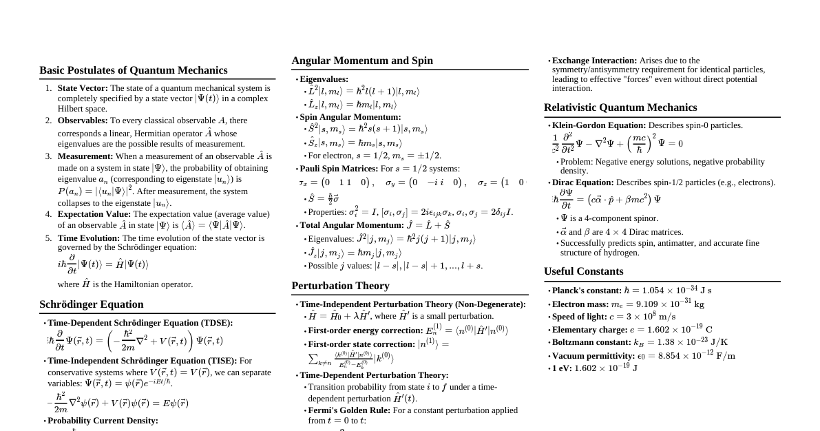
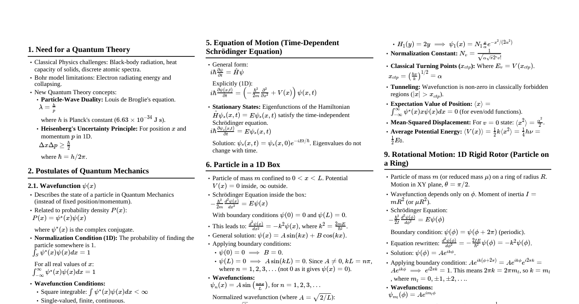
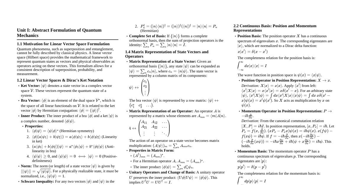
### Quantum Mechanics Fundamentals #### Time-Dependent Schrödinger Equation The time-dependent Schrödinger equation describes how the quantum state of a physical system evolves over time. $$i\hbar \frac{\partial}{\partial t} \Psi(\mathbf{r}, t) = \hat{H} \Psi(\mathbf{r}, t)$$ where $\hat{H}$ is the Hamiltonian operator, representing the total energy of the system. For a single particle of mass $m$ in a potential $V(\mathbf{r}, t)$: $$\hat{H} = -\frac{\hbar^2}{2m} \nabla^2 + V(\mathbf{r}, t)$$ #### Time-Independent Schrödinger Equation If the potential energy $V(\mathbf{r})$ is independent of time, the time-dependent Schrödinger equation can be separated into spatial and temporal parts. Let $\Psi(\mathbf{r}, t) = \psi(\mathbf{r}) e^{-iEt/\hbar}$. Substituting this into the time-dependent equation yields: $$-\frac{\hbar^2}{2m} \nabla^2 \psi(\mathbf{r}) + V(\mathbf{r}) \psi(\mathbf{r}) = E \psi(\mathbf{r})$$ This is the time-independent Schrödinger equation, where $E$ represents the total energy of the system. #### Particle in a One-Dimensional Box For a particle of mass $m$ confined to a region $0 #### Compton Effect When a photon scatters off a free electron, the photon loses some energy, resulting in an increase in its wavelength. This phenomenon demonstrates the particle nature of light. The change in wavelength (Compton shift) is given by: $$\Delta\lambda = \lambda' - \lambda = \frac{h}{m_e c}(1 - \cos\theta)$$ where: - $\Delta\lambda$ is the Compton wavelength shift - $\lambda$ is the incident photon wavelength - $\lambda'$ is the scattered photon wavelength - $h$ is Planck's constant - $m_e$ is the rest mass of the electron - $c$ is the speed of light - $\theta$ is the scattering angle of the photon The term $\frac{h}{m_e c}$ is known as the Compton wavelength ($\lambda_C \approx 2.426 \times 10^{-12}$ m). **Significance:** Confirmed the particle nature of light (photons) and the conservation of momentum and energy in photon-electron collisions. #### Compton Effect Calculations **Example 1: $\lambda = 0.0710 \text{ nm}$, $\theta = 60^\circ$** (i) Compton wavelength shift $\Delta\lambda$: $$\Delta\lambda = \frac{h}{m_e c}(1 - \cos\theta) = (2.426 \times 10^{-12} \text{ m})(1 - \cos 60^\circ)$$ $$\Delta\lambda = (2.426 \times 10^{-12} \text{ m})(1 - 0.5) = 1.213 \times 10^{-12} \text{ m} = 0.001213 \text{ nm}$$ (ii) Wavelength of the scattered photon $\lambda'$: $$\lambda' = \lambda + \Delta\lambda = 0.0710 \text{ nm} + 0.001213 \text{ nm} = 0.072213 \text{ nm}$$ **Example 2: $\lambda = 0.050 \text{ nm}$, $\theta = 90^\circ$, $\lambda_c = 2.426 \times 10^{-12} \text{ m}$** (i) Compton wavelength shift $\Delta\lambda$: $$\Delta\lambda = \lambda_c (1 - \cos\theta) = (2.426 \times 10^{-12} \text{ m})(1 - \cos 90^\circ)$$ $$\Delta\lambda = (2.426 \times 10^{-12} \text{ m})(1 - 0) = 2.426 \times 10^{-12} \text{ m} = 0.002426 \text{ nm}$$ (ii) Wavelength of the scattered photon $\lambda'$: $$\lambda' = \lambda + \Delta\lambda = 0.050 \text{ nm} + 0.002426 \text{ nm} = 0.052426 \text{ nm}$$ #### Black Body Radiation A **black body** is an idealized physical body that absorbs all incident electromagnetic radiation, regardless of frequency or angle of incidence. It emits thermal radiation in a continuous spectrum, known as black-body radiation. **Classical Theory Failure (Rayleigh-Jeans Law):** The Rayleigh-Jeans law, based on classical physics, predicted that the spectral radiance of a black body would increase indefinitely with frequency, leading to the "ultraviolet catastrophe" – an infinite amount of energy at high frequencies. This contradicted experimental observations, which showed the radiance peaking at a certain frequency and then decreasing. This failure paved the way for quantum mechanics. #### Heisenberg's Uncertainty Principle The Heisenberg Uncertainty Principle states that it is impossible to simultaneously know with perfect precision certain pairs of complementary properties of a particle, such as position and momentum, or energy and time. **Derivation (conceptual):** Consider a wave packet representing a particle. To localize the particle (small $\Delta x$), one needs to superimpose many waves of different wavelengths (large $\Delta p$). Conversely, a particle with a well-defined momentum (small $\Delta p$) is represented by a long wave train, meaning its position is poorly defined (large $\Delta x$). **Mathematical Form:** For position and momentum: $$\Delta x \Delta p_x \ge \frac{\hbar}{2}$$ For energy and time: $$\Delta E \Delta t \ge \frac{\hbar}{2}$$ where $\hbar = h/(2\pi)$ is the reduced Planck's constant. #### Uncertainty Principle Calculations **Example: Electron position accuracy $\Delta x = 0.1 \text{ nm}$, $m_e = 9.1 \times 10^{-31} \text{ kg}$, $h = 6.626 \times 10^{-34} \text{ J}\cdot\text{s}$** Minimum uncertainty in momentum $\Delta p_x$: $$\Delta p_x \ge \frac{\hbar}{2\Delta x} = \frac{h}{4\pi\Delta x}$$ $$\Delta p_x \ge \frac{6.626 \times 10^{-34} \text{ J}\cdot\text{s}}{4\pi (0.1 \times 10^{-9} \text{ m})} \approx 5.27 \times 10^{-25} \text{ kg}\cdot\text{m/s}$$ Corresponding uncertainty in velocity $\Delta v_x$: Since $\Delta p_x = m_e \Delta v_x$: $$\Delta v_x = \frac{\Delta p_x}{m_e} = \frac{5.27 \times 10^{-25} \text{ kg}\cdot\text{m/s}}{9.1 \times 10^{-31} \text{ kg}} \approx 5.79 \times 10^5 \text{ m/s}$$ ### Electromagnetism #### Maxwell's Equations Maxwell's equations are a set of four partial differential equations that, together with the Lorentz force law, form the foundation of classical electromagnetism, classical optics, and electric circuits. **Integral Form:** 1. **Gauss's Law for Electricity:** $\oint_S \mathbf{E} \cdot d\mathbf{A} = \frac{Q_{enc}}{\epsilon_0}$ (The electric flux through any closed surface is proportional to the total electric charge enclosed within that surface.) 2. **Gauss's Law for Magnetism:** $\oint_S \mathbf{B} \cdot d\mathbf{A} = 0$ (The magnetic flux through any closed surface is zero; magnetic monopoles do not exist.) 3. **Faraday's Law of Induction:** $\oint_C \mathbf{E} \cdot d\mathbf{l} = -\frac{d}{dt} \int_S \mathbf{B} \cdot d\mathbf{A}$ (A changing magnetic flux through a surface induces an electromotive force (EMF) in a closed loop bounding that surface.) 4. **Ampere-Maxwell Law:** $\oint_C \mathbf{B} \cdot d\mathbf{l} = \mu_0 I_{enc} + \mu_0 \epsilon_0 \frac{d}{dt} \int_S \mathbf{E} \cdot d\mathbf{A}$ (A magnetic field can be generated by an electric current or by a changing electric field (displacement current).) **Differential Form:** Using the divergence theorem and Stokes' theorem, the integral forms can be converted to differential forms: 1. **Gauss's Law for Electricity:** $\nabla \cdot \mathbf{E} = \frac{\rho}{\epsilon_0}$ 2. **Gauss's Law for Magnetism:** $\nabla \cdot \mathbf{B} = 0$ 3. **Faraday's Law of Induction:** $\nabla \times \mathbf{E} = -\frac{\partial \mathbf{B}}{\partial t}$ 4. **Ampere-Maxwell Law:** $\nabla \times \mathbf{B} = \mu_0 \mathbf{J} + \mu_0 \epsilon_0 \frac{\partial \mathbf{E}}{\partial t}$ where $\rho$ is the charge density and $\mathbf{J}$ is the current density. #### Electromagnetic Wave Equation in Free Space In free space (no charges $\rho=0$, no currents $\mathbf{J}=0$), Maxwell's equations become: 1. $\nabla \cdot \mathbf{E} = 0$ 2. $\nabla \cdot \mathbf{B} = 0$ 3. $\nabla \times \mathbf{E} = -\frac{\partial \mathbf{B}}{\partial t}$ 4. $\nabla \times \mathbf{B} = \mu_0 \epsilon_0 \frac{\partial \mathbf{E}}{\partial t}$ Taking the curl of Faraday's Law: $\nabla \times (\nabla \times \mathbf{E}) = \nabla \times \left(-\frac{\partial \mathbf{B}}{\partial t}\right) = -\frac{\partial}{\partial t}(\nabla \times \mathbf{B})$ Using the vector identity $\nabla \times (\nabla \times \mathbf{A}) = \nabla(\nabla \cdot \mathbf{A}) - \nabla^2 \mathbf{A}$ and substituting Ampere-Maxwell Law: $\nabla(\nabla \cdot \mathbf{E}) - \nabla^2 \mathbf{E} = -\frac{\partial}{\partial t}(\mu_0 \epsilon_0 \frac{\partial \mathbf{E}}{\partial t})$ Since $\nabla \cdot \mathbf{E} = 0$ in free space: $-\nabla^2 \mathbf{E} = -\mu_0 \epsilon_0 \frac{\partial^2 \mathbf{E}}{\partial t^2}$ $$\nabla^2 \mathbf{E} - \mu_0 \epsilon_0 \frac{\partial^2 \mathbf{E}}{\partial t^2} = 0$$ Similarly, for the magnetic field: $$\nabla^2 \mathbf{B} - \mu_0 \epsilon_0 \frac{\partial^2 \mathbf{B}}{\partial t^2} = 0$$ These are the **electromagnetic wave equations**. They are in the form of a general wave equation $\nabla^2 f - \frac{1}{v^2} \frac{\partial^2 f}{\partial t^2} = 0$, where $v$ is the wave speed. Thus, the speed of electromagnetic waves in free space is $v = \frac{1}{\sqrt{\mu_0 \epsilon_0}} = c$, the speed of light. #### Propagation of Electromagnetic Waves in Free Space In free space, electromagnetic waves propagate as transverse waves, meaning the oscillating electric ($\mathbf{E}$) and magnetic ($\mathbf{B}$) fields are perpendicular to each other and to the direction of propagation. - **Transverse Nature:** $\mathbf{E} \perp \mathbf{B}$ and both are perpendicular to the wave vector $\mathbf{k}$. - **Phase Relationship:** $\mathbf{E}$ and $\mathbf{B}$ fields oscillate in phase. - **Magnitude Relationship:** The magnitudes are related by $E = cB$. - **Speed:** They travel at the speed of light $c = 1/\sqrt{\mu_0 \epsilon_0}$. - **Absence of Medium:** They do not require a medium for propagation. - **Energy Transport:** Carry energy and momentum, described by the Poynting vector. #### Propagation of Electromagnetic Waves in Conducting Medium In a conducting medium, Maxwell's equations include the current density $\mathbf{J} = \sigma \mathbf{E}$ (Ohm's Law), where $\sigma$ is the conductivity. The Ampere-Maxwell Law becomes: $\nabla \times \mathbf{B} = \mu \sigma \mathbf{E} + \mu \epsilon \frac{\partial \mathbf{E}}{\partial t}$ Taking the curl, similar to free space derivation: $\nabla^2 \mathbf{E} - \mu \epsilon \frac{\partial^2 \mathbf{E}}{\partial t^2} - \mu \sigma \frac{\partial \mathbf{E}}{\partial t} = 0$ This is the wave equation for a conducting medium. Key characteristics: - **Attenuation:** The presence of the $\mu \sigma \frac{\partial \mathbf{E}}{\partial t}$ term leads to damping of the wave. The wave is exponentially attenuated as it propagates through the conductor. - **Phase Shift:** There is a phase difference between the $\mathbf{E}$ and $\mathbf{B}$ fields. - **Reduced Speed:** The speed of propagation is generally less than $c$. - **Skin Depth:** The wave penetrates only a small distance into the conductor, known as the skin depth ($\delta = \sqrt{\frac{2}{\omega \mu \sigma}}$), beyond which its amplitude significantly decreases. Good conductors reflect most of the incident EM wave. #### Poynting Theorem **Statement:** The Poynting theorem describes the conservation of energy for the electromagnetic field. It states that the rate of energy flow out of a given volume is equal to the rate of decrease in the electromagnetic energy stored within that volume minus the work done on the charges inside the volume. **Equation:** $$-\frac{\partial u_{EM}}{\partial t} = \nabla \cdot \mathbf{S} + \mathbf{J} \cdot \mathbf{E}$$ where: - $u_{EM} = \frac{1}{2}(\epsilon_0 E^2 + \frac{1}{\mu_0} B^2)$ is the electromagnetic energy density. - $\mathbf{S} = \frac{1}{\mu_0}(\mathbf{E} \times \mathbf{B})$ is the **Poynting vector**. - $\mathbf{J} \cdot \mathbf{E}$ is the rate at which the electromagnetic field does work on the charges (power dissipated per unit volume). **Physical Meaning of the Poynting Vector ($\mathbf{S}$):** The Poynting vector represents the directional energy flux (power per unit area) of an electromagnetic field. - **Magnitude:** Its magnitude indicates the rate at which electromagnetic energy flows through a unit area perpendicular to the direction of propagation. - **Direction:** Its direction is the direction of energy propagation. For a plane wave, $\mathbf{S}$ is in the direction of wave propagation. #### Displacement Current **What is it?** The displacement current ($I_D$) is a term introduced by James Clerk Maxwell into Ampere's Law to account for changing electric fields. It is not a current of moving charges, but rather a conceptual current representing a changing electric flux. **Why it was introduced by Maxwell:** 1. **Consistency with Charge Conservation:** Ampere's Law ($\oint_C \mathbf{B} \cdot d\mathbf{l} = \mu_0 I_{enc}$) is inconsistent with the continuity equation for charge conservation ($\nabla \cdot \mathbf{J} = -\frac{\partial \rho}{\partial t}$) when applied to time-varying fields, especially in circuits with capacitors. For example, a capacitor being charged has current flowing into one plate, but no conduction current through the dielectric. Ampere's Law would predict a magnetic field around the wire but not around the gap. 2. **Symmetry of Maxwell's Equations:** Without the displacement current, Faraday's Law describes how a changing magnetic field produces an electric field, but there was no corresponding term for how a changing electric field produces a magnetic field. Introducing the displacement current made the equations symmetric. 3. **Prediction of EM Waves:** The inclusion of the displacement current term was crucial for Maxwell to theoretically predict the existence of electromagnetic waves propagating at the speed of light. **Mathematical Expression:** The displacement current density $\mathbf{J}_D$ is given by: $$\mathbf{J}_D = \epsilon_0 \frac{\partial \mathbf{E}}{\partial t}$$ The total displacement current $I_D$ through a surface $S$ is: $$I_D = \int_S \mathbf{J}_D \cdot d\mathbf{A} = \int_S \epsilon_0 \frac{\partial \mathbf{E}}{\partial t} \cdot d\mathbf{A} = \epsilon_0 \frac{d}{dt} \int_S \mathbf{E} \cdot d\mathbf{A} = \epsilon_0 \frac{d\Phi_E}{dt}$$ where $\Phi_E$ is the electric flux. ### Optics: Interference #### Newton's Rings **Setup:** Newton's rings are an interference pattern caused by the reflection of light between two surfaces: a spherical surface (plano-convex lens with a large radius of curvature) and an adjacent flat surface (flat glass plate). The lens is placed on the plate, creating a thin, wedge-shaped air film of varying thickness between them. When monochromatic light is incident normally on this setup, concentric bright and dark rings are observed. The rings are centered at the point of contact, where the air film thickness is zero. **Derivation for Wavelength of Light:** For destructive interference (dark rings), the path difference $2t$ (where $t$ is the thickness of the air film) must be an integer multiple of the wavelength plus a $\lambda/2$ phase shift upon reflection from the top surface of the glass plate (denser medium). So for dark rings: $2t = m\lambda$, where $m = 0, 1, 2, ...$ From geometry, for a plano-convex lens of radius of curvature $R$ and a ring of radius $r$, the thickness of the air film $t$ at radius $r$ is approximately $t = \frac{r^2}{2R}$. Substituting $t$ into the condition for dark rings: $$2\left(\frac{r_m^2}{2R}\right) = m\lambda$$ $$r_m^2 = mR\lambda$$ The radius of the $m$-th dark ring is $r_m = \sqrt{mR\lambda}$. Thus, the wavelength of light can be determined by measuring the radii of the dark rings and the radius of curvature of the lens: $$\lambda = \frac{r_m^2}{mR}$$ #### Newton's Rings Calculation **Example: $R = 1.00 \text{ m}$, $\lambda = 589 \text{ nm}$. Calculate radius of 10th dark ring ($m=10$).** $$r_{10} = \sqrt{10 R \lambda}$$ $$r_{10} = \sqrt{10 \times (1.00 \text{ m}) \times (589 \times 10^{-9} \text{ m})}$$ $$r_{10} = \sqrt{5890 \times 10^{-9} \text{ m}^2} = \sqrt{5.89 \times 10^{-6} \text{ m}^2}$$ $$r_{10} \approx 2.427 \times 10^{-3} \text{ m} = 2.427 \text{ mm}$$ #### Interference of Light **Definition:** Interference of light is the phenomenon where two or more light waves superpose to form a resultant wave of greater, lower, or the same amplitude. This results in a characteristic pattern of bright and dark fringes (maxima and minima). **Principle of Superposition:** When two or more waves overlap in space, the resultant displacement at any point and at any instant is the vector sum of the displacements due to the individual waves at that point and instant. $$y_{resultant} = y_1 + y_2 + ... + y_n$$ **Essential Conditions for Sustained Interference:** For a stable and observable interference pattern (sustained interference), the light sources must meet the following conditions: 1. **Coherence:** The sources must be coherent, meaning they emit waves with a constant phase difference (and ideally, the same frequency). This is usually achieved by deriving two waves from a single source (e.g., by splitting a wavefront or amplitude). 2. **Monochromaticity:** The light should be monochromatic (single wavelength/frequency). If not, different wavelengths will produce different fringe patterns, which overlap and blur the overall pattern. 3. **Close Proximity:** The sources (or virtual sources) should be close to each other to ensure a sufficiently large fringe width and to minimize the angular separation of fringes, making them observable. 4. **Narrow Sources:** The sources should be narrow (point sources or narrow slits) to ensure that the light waves are approximately spherical or cylindrical and can constructively and destructively interfere effectively. 5. **Equal Amplitude (for high contrast):** While not strictly essential for interference, for a high-contrast pattern with clearly distinguishable bright and dark fringes, the interfering waves should have nearly equal amplitudes. #### Thin Film Interference **Explanation:** Thin film interference occurs when light waves reflecting from the top and bottom surfaces of a thin transparent film (like an oil slick or a soap bubble) interfere with each other. The path difference between these reflected waves, combined with any phase changes upon reflection, determines whether constructive or destructive interference occurs. **Conditions:** - **Path Difference:** The light reflected from the bottom surface travels an extra distance within the film (approximately $2t$, where $t$ is the film thickness) compared to the light reflected from the top surface. - **Phase Change on Reflection:** A phase change of $\pi$ radians (or $180^\circ$) occurs when light reflects from an interface with a medium of higher refractive index. - If light goes from a less dense to a more dense medium (e.g., air to oil), a $\pi$ phase change occurs. - If light goes from a more dense to a less dense medium (e.g., oil to air), no phase change occurs. **Derivation for Destructive Interference (Normal Incidence):** Consider a thin film of refractive index $n_f$ surrounded by media with refractive indices $n_1$ (incident side) and $n_2$ (transmitted side). Assume $n_1 n_2$ (e.g., air-oil-water) or $n_1 n_2$ (e.g., air-oil-water). 1. Light ray 1 reflects from the top surface (air-oil). Since $n_{air} n_{water}$, no phase change occurs. The path difference in the film is $2n_f t$ (where $n_f$ is the refractive index of the film). For **destructive interference**: The total phase difference must be an odd multiple of $\pi$. The phase change from reflection is $\pi$. So, for destructive interference, the path difference must be an integer multiple of $\lambda_{film}$. $$2n_f t = m\lambda$$ (where $\lambda$ is the wavelength in vacuum, $m = 0, 1, 2, ...$) This means the path difference (in terms of wavelength) must exactly cancel the $\pi$ phase shift from reflection. If $n_1 #### Thin Film Interference Calculation **Example: Oil film on water, $n_{oil} = 1.40$, $\lambda = 520 \text{ nm}$. Find least thickness for destructive interference.** Assume $n_{air} = 1.0$, $n_{water} \approx 1.33$. So, $n_{air} n_{water}$. Reflection 1 (air-oil): $\pi$ phase change. Reflection 2 (oil-water): No phase change (since $n_{oil} > n_{water}$). For destructive interference, the path difference must be an integer multiple of $\lambda$. $$2n_{oil} t = m\lambda$$ For the least thickness, we take $m=0$. $$2n_{oil} t = \lambda$$ $$t = \frac{\lambda}{2n_{oil}} = \frac{520 \times 10^{-9} \text{ m}}{2 \times 1.40}$$ $$t = \frac{520 \times 10^{-9}}{2.8} \text{ m} \approx 1.857 \times 10^{-7} \text{ m} = 185.7 \text{ nm}$$ ### Optics: Diffraction #### Intensity of Light for Diffraction Through a Single Slit When monochromatic light passes through a single narrow slit, it deviates from straight-line propagation and spreads out, creating a diffraction pattern of bright and dark fringes on a screen. The intensity distribution $I(\theta)$ for a single slit of width $a$ is given by: $$I(\theta) = I_0 \left(\frac{\sin\alpha}{\alpha}\right)^2$$ where: - $I_0$ is the maximum intensity at the center of the pattern ($\theta = 0$). - $\alpha = \frac{\pi a}{\lambda} \sin\theta$. - $a$ is the width of the slit. - $\lambda$ is the wavelength of light. - $\theta$ is the angle from the central maximum to the point of observation on the screen. **Minima (Dark Fringes):** Occur when $\sin\alpha = 0$, but $\alpha \ne 0$. This happens when $\alpha = m\pi$, where $m = \pm 1, \pm 2, \pm 3, ...$ Substituting $\alpha$: $$\frac{\pi a}{\lambda} \sin\theta = m\pi$$ $$a \sin\theta = m\lambda \quad \text{(for minima)}$$ **Maxima (Bright Fringes):** Occur approximately halfway between the minima. The central maximum is the brightest and widest. Secondary maxima are much less intense and narrower. #### Diffraction Grating **Explanation:** A diffraction grating is an optical component with a periodic structure, typically a large number of closely spaced parallel lines or grooves, that diffracts light into several beams traveling in different directions. The directions of these beams depend on the spacing of the grating and the wavelength of the light. Gratings are used to disperse light into its constituent wavelengths (like a prism) and are fundamental in spectrometers. **Grating Equation:** For normal incidence, the condition for constructive interference (bright fringes or principal maxima) for a diffraction grating with grating element $d$ (distance between centers of adjacent slits) is: $$d \sin\theta = m\lambda$$ where: - $d = 1/N$, where $N$ is the number of lines per unit length. - $\theta$ is the diffraction angle for the $m$-th order maximum. - $m = 0, \pm 1, \pm 2, ...$ (order of the maximum). - $\lambda$ is the wavelength of light. **Resolving Power of a Diffraction Grating:** The resolving power ($R$) of a diffraction grating is a measure of its ability to distinguish between two closely spaced wavelengths ($\lambda$ and $\lambda + \Delta\lambda$). It is defined as: $$R = \frac{\lambda}{\Delta\lambda}$$ **Derivation:** The resolving power for the $m$-th order maximum is also given by: $$R = Nm$$ where: - $N$ is the total number of illuminated lines (slits) on the grating. - $m$ is the order of the spectrum. This expression shows that to achieve high resolving power, one needs a grating with a large number of lines and/or to observe higher-order spectra. A larger number of lines means a narrower maximum, allowing better separation of closely spaced wavelengths. #### Rayleigh Criterion **Statement:** The Rayleigh criterion specifies the minimum angular separation between two point sources that can be resolved by an optical instrument. According to this criterion, two point sources are just resolvable when the center of the diffraction pattern of one source is directly over the first minimum of the diffraction pattern of the other source. **Significance:** - **Limit of Resolution:** It sets a fundamental limit on the resolving power of optical instruments (telescopes, microscopes, human eye) due to the wave nature of light and diffraction effects. - **Angular Resolution:** For a circular aperture of diameter $D$, the minimum angular separation $\theta_{min}$ (in radians) for two sources to be just resolved is: $$\theta_{min} = 1.22 \frac{\lambda}{D}$$ where $\lambda$ is the wavelength of light. - **Impact on Design:** This criterion is crucial in the design and evaluation of optical systems, determining how fine a detail can be observed or how close two objects can be and still appear distinct. For example, larger telescope mirrors (larger $D$) have better angular resolution. ### Optical Fibers #### Principle and Construction of Optical Fiber **Principle:** Optical fibers work on the principle of **Total Internal Reflection (TIR)**. When light travels from a denser medium (higher refractive index) to a rarer medium (lower refractive index) at an angle of incidence greater than the critical angle, it is entirely reflected back into the denser medium. **Construction:** An optical fiber typically consists of three main concentric layers: 1. **Core:** The innermost part, usually made of high-quality glass (silica) or plastic, with a higher refractive index ($n_1$). This is the region where light propagates. 2. **Cladding:** Surrounds the core and is also made of glass or plastic, but with a slightly lower refractive index ($n_2 #### Principle of Optical Fiber Communication Optical fiber communication involves transmitting information (data, voice, video) through optical fibers in the form of light pulses. **Basic Principle:** 1. **Electrical-to-Optical Conversion:** An electrical signal (representing information) is converted into an optical signal (light pulses) by an optical transmitter, typically a Light Emitting Diode (LED) or a laser diode. 2. **Light Transmission:** These light pulses are launched into the core of an optical fiber. Due to Total Internal Reflection (TIR) at the core-cladding interface, the light pulses are guided along the length of the fiber with minimal loss, even around bends. 3. **Optical-to-Electrical Conversion:** At the receiving end, an optical receiver (photodetector, e.g., photodiode) converts the optical pulses back into an electrical signal. 4. **Signal Processing:** The electrical signal is then processed to reconstruct the original information. **Advantages:** High bandwidth, low signal loss, immunity to electromagnetic interference, lightweight, secure. #### Numerical Aperture of an Optical Fiber **Derivation:** The numerical aperture (NA) is a measure of the light-gathering ability of an optical fiber. It describes the maximum angle at which light can enter the fiber and still be guided by total internal reflection. Consider a light ray entering the fiber from air ($n_0 \approx 1$) at an angle $\theta_a$ to the fiber axis. It refracts at the air-core interface and enters the core at angle $\theta_r$. By Snell's Law at the air-core interface: $n_0 \sin\theta_a = n_1 \sin\theta_r$. For total internal reflection to occur at the core-cladding interface, the angle of incidence $\phi$ at this interface must be greater than or equal to the critical angle $\phi_c$. The critical angle is given by $\sin\phi_c = \frac{n_2}{n_1}$. From geometry, $\theta_r + \phi = 90^\circ$, so $\sin\theta_r = \cos\phi$. For TIR, $\phi \ge \phi_c$, which means $\cos\phi \le \cos\phi_c$. So, $\sin\theta_r \le \cos\phi_c = \sqrt{1 - \sin^2\phi_c} = \sqrt{1 - \left(\frac{n_2}{n_1}\right)^2}$. Substituting this back into Snell's Law: $n_0 \sin\theta_a \le n_1 \sqrt{1 - \left(\frac{n_2}{n_1}\right)^2}$ $n_0 \sin\theta_a \le \sqrt{n_1^2 - n_2^2}$ The maximum acceptance angle $\theta_a^{max}$ occurs when the equality holds. The numerical aperture (NA) is defined as $n_0 \sin\theta_a^{max}$. $$NA = \sqrt{n_1^2 - n_2^2}$$ For air ($n_0=1$): $$NA = \sin\theta_a^{max} = \sqrt{n_1^2 - n_2^2}$$ where $n_1$ is the refractive index of the core and $n_2$ is the refractive index of the cladding. #### Numerical Aperture Calculation **Example: Acceptance half-angle $\theta_a = 30^\circ$, $n_2 = 1.44$. Determine minimum core refractive index $n_1$.** Given $NA = \sin\theta_a = \sin 30^\circ = 0.5$. We know $NA = \sqrt{n_1^2 - n_2^2}$. So, $0.5 = \sqrt{n_1^2 - (1.44)^2}$ Squaring both sides: $0.25 = n_1^2 - (1.44)^2$ $0.25 = n_1^2 - 2.0736$ $n_1^2 = 0.25 + 2.0736 = 2.3236$ $n_1 = \sqrt{2.3236} \approx 1.524$ The minimum core refractive index $n_1$ must be approximately $1.524$. ### Lasers #### Einstein Relations Between Coefficients Einstein's theory of radiation describes the interaction of electromagnetic radiation with matter, specifically the processes of absorption, spontaneous emission, and stimulated emission. He introduced three coefficients: - $B_{12}$: Probability of absorption from state 1 to state 2 per unit energy density. - $A_{21}$: Probability of spontaneous emission from state 2 to state 1 per unit time. - $B_{21}$: Probability of stimulated emission from state 2 to state 1 per unit energy density. **Derivation (Conceptual):** At thermal equilibrium, the rates of upward transitions (absorption) must equal the rates of downward transitions (spontaneous + stimulated emission). Let $N_1$ and $N_2$ be the populations of the lower (1) and upper (2) energy levels, respectively. Let $u(\nu)$ be the energy density of radiation at frequency $\nu$. Rate of absorption = $N_1 B_{12} u(\nu)$ Rate of spontaneous emission = $N_2 A_{21}$ Rate of stimulated emission = $N_2 B_{21} u(\nu)$ At equilibrium: $N_1 B_{12} u(\nu) = N_2 A_{21} + N_2 B_{21} u(\nu)$ Also, at thermal equilibrium, the population ratio follows Boltzmann distribution: $N_2/N_1 = e^{-\frac{E_2 - E_1}{kT}} = e^{-\frac{h\nu}{kT}}$. By comparing this with Planck's radiation law for $u(\nu)$, Einstein derived the following relations: 1. **$B_{12} = B_{21}$** (The probability of absorption is equal to the probability of stimulated emission). 2. **$\frac{A_{21}}{B_{21}} = \frac{8\pi h\nu^3}{c^3}$** (Relates spontaneous and stimulated emission probabilities). These relations are fundamental to understanding laser action, particularly the need for population inversion to overcome spontaneous emission and achieve net stimulated emission. #### Absorption, Spontaneous Emission, and Stimulated Emission 1. **Absorption:** - **Process:** An atom in a lower energy state (E1) absorbs a photon of energy $h\nu = E_2 - E_1$ and transitions to a higher energy state (E2). - **Requirement:** Presence of incident radiation. - **Outcome:** Decreases the intensity of the incident radiation. 2. **Spontaneous Emission:** - **Process:** An atom in an excited state (E2) spontaneously (without external trigger) transitions to a lower energy state (E1), emitting a photon of energy $h\nu = E_2 - E_1$. - **Requirement:** Atom must be in an excited state. No external field is needed. - **Characteristics:** The emitted photons are random in direction, phase, and polarization (incoherent). - **Outcome:** Contributes to incoherent light sources (e.g., incandescent bulbs, LEDs). 3. **Stimulated Emission:** - **Process:** An atom in an excited state (E2) is perturbed by an incident photon of energy $h\nu = E_2 - E_1$. This incident photon "stimulates" the excited atom to transition to a lower energy state (E1), emitting an identical photon. - **Requirement:** Atom must be in an excited state AND an incident photon of the correct energy must be present. - **Characteristics:** The emitted photon is identical to the incident photon in terms of energy, direction, phase, and polarization (coherent). - **Outcome:** This is the fundamental process responsible for light amplification in lasers, leading to coherent, monochromatic, and directional light. #### Population Inversion and Optical Pumping 1. **Population Inversion:** - **Concept:** In thermal equilibrium, the number of atoms in a lower energy state ($N_1$) is always greater than the number of atoms in a higher energy state ($N_2$) (i.e., $N_1 > N_2$). - **Requirement for Laser:** For stimulated emission to dominate over absorption and achieve net light amplification (laser action), the population of the upper energy state must be greater than the population of the lower energy state ($N_2 > N_1$). This non-equilibrium condition is called **population inversion**. - **Why:** If $N_1 > N_2$, absorption would be more likely than stimulated emission, and the incident light would be absorbed rather than amplified. 2. **Optical Pumping:** - **Concept:** Optical pumping is a method used to achieve population inversion in a laser medium. It involves using light (photons) from an external source to excite atoms from a lower energy level to a higher energy level. - **Process:** - The laser medium (gain medium) is irradiated with light (e.g., from a flash lamp or another laser). - Atoms absorb these "pump" photons and are excited to a high energy level. - These atoms then quickly undergo non-radiative transitions (e.g., by collisions) to a metastable energy level (an excited state with a relatively long lifetime). - If enough atoms accumulate in this metastable level, and the lower laser level is relatively empty, population inversion is achieved between the metastable level and a lower-lying level, enabling stimulated emission. - **Examples:** Flash lamps in solid-state lasers (like Ruby laser), diode lasers in fiber lasers. #### Basic Requirements of a Laser System and Principle of Laser Action **Basic Requirements of a Laser System:** 1. **Gain Medium (Active Medium):** A material (solid, liquid, gas, semiconductor) that contains atoms, ions, or molecules capable of being excited to higher energy levels and sustaining population inversion. This is where light amplification occurs. 2. **Energy Pump Source:** An external energy source (e.g., electrical discharge, flash lamp, another laser) to excite the atoms in the gain medium and achieve population inversion. 3. **Optical Resonator (Resonant Cavity):** Typically consists of two highly reflective mirrors placed at opposite ends of the gain medium. This cavity provides positive feedback, allowing emitted photons to reflect back and forth through the gain medium, stimulating further emission and creating an amplification effect. One mirror is fully reflective, and the other is partially reflective to allow a portion of the amplified light to escape as the laser beam. **Principle of Laser Action (Light Amplification by Stimulated Emission of Radiation):** 1. **Pumping:** The energy pump excites atoms in the gain medium to higher energy levels, creating a population inversion ($N_2 > N_1$). 2. **Spontaneous Emission:** A few excited atoms spontaneously drop to a lower energy level, emitting photons randomly. 3. **Stimulated Emission:** If a spontaneously emitted photon (or an external seed photon) travels through the gain medium and encounters another excited atom, it stimulates that atom to emit an identical photon. Crucially, this new photon is in phase, in the same direction, and has the same polarization as the stimulating photon. This leads to a cascade effect. 4. **Amplification in Resonator:** These coherent photons travel back and forth between the mirrors of the optical resonator. As they pass through the gain medium, they stimulate more emissions, leading to a rapid increase in the number of identical photons. 5. **Output Coupling:** One of the mirrors is partially transparent, allowing a fraction of the highly amplified, coherent light to escape as the laser beam. The remaining light continues to oscillate within the cavity, sustaining the process. #### Construction and Working of Ruby Laser The Ruby laser was the first operational laser, developed by Maiman in 1960. It is a solid-state, three-level laser. **Construction:** 1. **Gain Medium:** A synthetic ruby crystal (aluminum oxide, $\text{Al}_2\text{O}_3$, doped with about 0.05% chromium ions, $\text{Cr}^{3+}$). The $\text{Cr}^{3+}$ ions are the active centers. The ends of the ruby rod are polished flat and parallel, and often silvered to act as the resonant cavity mirrors (one fully reflective, one partially reflective). 2. **Pump Source:** A high-intensity photographic flash lamp (e.g., xenon flash tube) coiled around the ruby rod. 3. **Optical Resonator:** Provided by the silvered ends of the ruby rod itself, or by external mirrors. **Working (Three-Level System):** 1. **Pumping:** The flash lamp emits intense white light. The $\text{Cr}^{3+}$ ions in the ruby crystal absorb green and blue light (around 400 nm and 550 nm) from the flash lamp, exciting them from the ground state ($E_1$) to a broad pump band ($E_3$). 2. **Non-Radiative Transition:** From the pump band ($E_3$), the $\text{Cr}^{3+}$ ions rapidly (in picoseconds) undergo a non-radiative transition (losing energy as heat to the crystal lattice) to a metastable energy level ($E_2$). This level has a relatively long lifetime ($\sim 3$ ms). 3. **Population Inversion:** Due to the long lifetime of $E_2$ and continuous pumping, a significant number of $\text{Cr}^{3+}$ ions accumulate in $E_2$, leading to population inversion between $E_2$ and the ground state $E_1$. 4. **Stimulated Emission:** When a spontaneously emitted photon (with energy corresponding to $E_2 - E_1$, around 694.3 nm, red light) travels along the axis of the ruby rod, it stimulates other excited $\text{Cr}^{3+}$ ions in $E_2$ to emit identical photons. 5. **Laser Output:** These photons are reflected back and forth by the mirrors, amplifying the light through further stimulated emission. When the amplified light beam becomes sufficiently intense, it escapes through the partially reflective mirror as a pulsed red laser beam. ### Solid State Physics #### Superconductivity **Concept:** Superconductivity is a phenomenon observed in certain materials below a characteristic critical temperature ($T_c$), where they exhibit precisely zero electrical resistance and expel magnetic fields (Meissner effect). **Meissner Effect:** - **Description:** When a superconductor is cooled below its critical temperature in the presence of an external magnetic field, it expels all magnetic flux from its interior. The magnetic field lines are pushed out of the material. - **Significance:** This is a defining characteristic of superconductivity, distinguishing it from a perfect conductor (which would only prevent changes in magnetic flux, but not expel existing flux). It implies that superconductors are perfect diamagnets. **Type I Superconductors:** - **Characteristics:** - Exhibit a sharp transition to the superconducting state. - Completely expel magnetic fields (Meissner effect) below $T_c$ and a critical magnetic field ($H_c$). - Below $H_c$, they are perfect diamagnets; above $H_c$, superconductivity is destroyed. - Typically pure metals (e.g., Al, Pb, Hg). - **Applications:** Limited practical applications due to low $T_c$ and low $H_c$. Used in sensitive magnetometers, SQUIDs. **Type II Superconductors:** - **Characteristics:** - Exhibit two critical magnetic fields: $H_{c1}$ and $H_{c2}$. - Below $H_{c1}$: Complete Meissner effect, perfect diamagnetism. - Between $H_{c1}$ and $H_{c2}$ (Mixed State or Vortex State): The magnetic field partially penetrates the material in the form of quantized flux lines (vortices). The material is still superconducting, but with some magnetic field present. - Above $H_{c2}$: Superconductivity is destroyed. - Typically alloys or ceramic materials (e.g., NbTi, YBCO). - **Applications:** Far more practical due to much higher $T_c$ and very high $H_{c2}$ (can sustain superconductivity in strong magnetic fields). Used in high-field electromagnets (MRI, NMR, particle accelerators), power transmission lines, magnetic levitation (Maglev trains). #### Free Electron Theory of Metals **Description:** The free electron theory (FET) of metals, primarily developed by Drude and Sommerfeld, aims to explain the electrical and thermal properties of metals. **Drude's Theory (Classical Free Electron Theory):** - **Assumptions:** - Metals contain a "gas" of free electrons that move randomly, like classical gas molecules. - Positive ions are fixed in a lattice. - Electrons collide with ions (or defects), but not with each other. - Electron motion is governed by classical mechanics. - **Successes:** Explained Ohm's law, electrical and thermal conductivity, and the Wiedemann-Franz law. - **Failures:** - Incorrectly predicted specific heat capacity of electrons (observed much smaller than predicted). - Failed to explain the temperature dependence of resistivity. - Failed to explain the positive Hall coefficient observed in some metals. - Did not account for ferromagnetism. **Sommerfeld's Model (Quantum Free Electron Theory):** - **Improvement upon Drude's Theory:** Sommerfeld retained the "free electron gas" concept but replaced classical mechanics with quantum mechanics (Fermi-Dirac statistics). - **Key Changes/Improvements:** 1. **Fermi-Dirac Statistics:** Electrons are fermions and obey Pauli's exclusion principle. They occupy energy levels up to the Fermi energy ($E_F$) even at absolute zero. Only electrons near $E_F$ can participate in conduction and contribute to specific heat. 2. **Quantized Energy Levels:** Electron energies are quantized. 3. **Mean Free Path:** The mean free path of electrons is much longer than predicted by Drude, as electron-electron collisions are less frequent due to Pauli exclusion. 4. **Specific Heat Capacity:** Successfully explained the very small electronic contribution to specific heat capacity, as only a small fraction of electrons near $E_F$ can be excited thermally. 5. **Temperature Dependence of Resistivity:** Provided a better explanation for the temperature dependence of resistivity (though still not perfect for all metals). - **Remaining Limitations:** Still treats the electrons as entirely free, ignoring the periodic potential of the crystal lattice. This limitation was addressed by the band theory of solids. #### PN Junction Diode with V-I Characteristics & Nanomaterials **PN Junction Diode:** - **Formation:** A PN junction diode is formed by joining a p-type semiconductor (doped with acceptor impurities, creating holes) with an n-type semiconductor (doped with donor impurities, creating free electrons). - **Depletion Region:** At the junction, electrons from the n-side diffuse to the p-side and recombine with holes, creating a region devoid of free charge carriers called the depletion region. This region contains immobile ionized dopants, creating an internal electric field (built-in potential barrier). - **V-I Characteristics:** - **Forward Bias:** When a positive voltage is applied to the p-side and negative to the n-side, the external voltage opposes the built-in potential. The depletion region narrows, allowing current to flow exponentially once the "cut-in" or "threshold" voltage is overcome (typically 0.7V for Si, 0.3V for Ge). - **Reverse Bias:** When a positive voltage is applied to the n-side and negative to the p-side, the external voltage adds to the built-in potential. The depletion region widens, and only a very small leakage current flows. - **Breakdown:** If the reverse bias voltage is increased sufficiently, the diode undergoes breakdown (Zener or avalanche), where a large current flows, potentially damaging the device. **Nanomaterials and Their Applications:** - **Definition:** Nanomaterials are materials with at least one dimension in the nanoscale (typically 1 to 100 nanometers). At this scale, materials exhibit unique physical, chemical, and biological properties that differ significantly from their bulk counterparts due to quantum mechanical effects and increased surface-to-volume ratio. - **Applications:** 1. **Electronics:** Quantum dots (LEDs, displays), carbon nanotubes (transistors, interconnects), graphene (high-speed electronics). 2. **Medicine:** Drug delivery systems (nanoparticles encapsulate drugs), medical diagnostics (nanosensors, contrast agents), cancer therapy (hyperthermia, targeted drug delivery). 3. **Energy:** Solar cells (enhanced efficiency), catalysts (increased surface area), batteries (higher energy density, faster charging), hydrogen storage. 4. **Coatings & Composites:** Scratch-resistant coatings, self-cleaning surfaces, stronger and lighter composites (e.g., carbon nanotube reinforced polymers). 5. **Environmental:** Water purification (nanofiltration membranes, photocatalysts), pollution detection (nanosensors). #### Semiconductors **What are Semiconductors?** Semiconductors are materials that have electrical conductivity between that of a conductor (like metals) and an insulator (like glass). Their electrical properties can be significantly altered by doping (introducing impurities) or by changing temperature or light exposure. **Two Types of Semiconductors:** 1. **Intrinsic Semiconductors:** - **Explanation:** These are pure semiconductors (e.g., pure silicon (Si) or germanium (Ge)) with no added impurities. - **Mechanism:** At absolute zero (0 K), they behave like insulators. At room temperature, thermal energy breaks some covalent bonds, creating electron-hole pairs. The electrons in the conduction band and holes in the valence band contribute equally to conduction. - **Charge Carriers:** The number of free electrons is equal to the number of holes ($n_e = n_h = n_i$, where $n_i$ is the intrinsic carrier concentration). - **Conductivity:** Relatively low conductivity, highly dependent on temperature. 2. **Extrinsic Semiconductors:** - **Explanation:** These are semiconductors that have been intentionally doped with impurities to modify their electrical conductivity. Doping significantly increases the number of majority charge carriers. - **Types:** a. **N-type Semiconductor:** - **Doping:** Doped with pentavalent impurities (e.g., Phosphorus, Arsenic) from Group 15 of the periodic table. These impurities have 5 valence electrons. - **Mechanism:** Four valence electrons form covalent bonds with the semiconductor atoms, leaving one extra electron that is loosely bound and easily becomes a free electron in the conduction band. - **Charge Carriers:** Electrons are the majority carriers, and holes are the minority carriers ($n_e \gg n_h$). - **Donors:** The pentavalent impurities are called donor impurities because they "donate" free electrons. b. **P-type Semiconductor:** - **Doping:** Doped with trivalent impurities (e.g., Boron, Aluminum) from Group 13 of the periodic table. These impurities have 3 valence electrons. - **Mechanism:** The three valence electrons form covalent bonds, but one bond is incomplete, creating a "hole" (a vacancy for an electron). This hole can easily accept an electron from a neighboring atom, effectively causing the hole to move. - **Charge Carriers:** Holes are the majority carriers, and electrons are the minority carriers ($n_h \gg n_e$). - **Acceptors:** The trivalent impurities are called acceptor impurities because they "accept" electrons (or create holes).