Power Electronics Essentials
Shared 5/11/2026•0 views
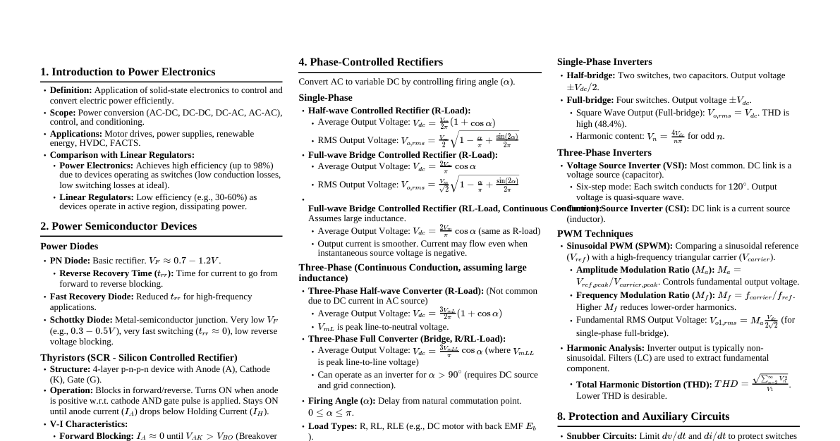
### Power Electronic Circuits Power electronic circuits can be classified into: - **Phase controlled rectifier:** Fixed AC to variable DC. - **Inverters:** Fixed DC to variable AC (variable V or f). - **Choppers:** Fixed DC to variable DC. - **Voltage controllers:** Fixed AC to variable AC (variable V; fixed f). - **Cycloconverters & Matrix converters:** Fixed AC to variable AC (variable V or f). ### Role in Sustainable Electric Energy Power electronics play a crucial role in: - **Electric-Motor Driven Systems:** Adjustable-speed drives reduce energy consumption. - **Lighting:** High-frequency CFLs and LEDs. - **Transportation:** Electric and Hybrid Electric Vehicles. - **Renewable Energy:** Interfacing wind-electric systems and photovoltaic systems to the utility grid. - **Distributed Generation:** Interfacing nonconventional energy sources (wind, PV, fuel cells). - **Power Flow Control:** Allows control over power on transmission lines. - **Uninterruptible Power Supplies (UPS):** For critical loads. - **Space Exploration & Interplanetary Travel.** - **Aerospace & Marine:** Replacement of hydraulic drives with electric drives for cost/weight reduction. ### High Efficiency & Power Density Power electronic systems must be: - **Energy efficient:** Lowers operating costs, reduces global warming, and decreases cooling needs. - **Reliable:** Ensures consistent operation. - **High power density:** Reduces size and weight. - **Low cost:** Economically feasible. ### Ideal and Practical Switches #### Ideal Switch - **On-state:** Zero voltage drop, infinite current handling. - **Off-state:** Infinite resistance, zero leakage current. - **Switching speed:** Instantaneous turn-on/off. - **Power loss:** Zero. #### Practical Switch - **On-state:** Non-zero voltage drop, finite on-state resistance ($R_{on}$), leading to conduction loss. - **Off-state:** Finite off-state resistance, non-zero leakage current, leading to power loss when off. - **Switching speed:** Finite turn-on ($t_{on}$) and turn-off ($t_{off}$) times, limiting max switching frequency. - **Power loss:** Conduction loss (due to $R_{on}$) and switching loss (due to finite switching times). - **Other limitations:** Limited voltage/current ratings, limited rates of change for current (di/dt) and voltage (dv/dt). ### Dynamic Performance of Switch - An ideal switch changes state instantaneously. - Real switches have finite $t_{on}$ and $t_{off}$, which: 1. Limit highest repetitive switching frequencies. 2. Introduce additional power dissipation. ### Power Losses and Temperature Rise #### Types of Losses - **Conduction Losses (Static):** Power dissipated due to finite voltage drop and current flow during ON state. - **Switching Losses (Dynamic):** Power dissipated during non-zero transition times (ON/OFF states). - **Leakage Losses (Static):** Power dissipated due to small leakage current in OFF state (usually negligible). #### Temperature Rise - All power losses convert to heat, increasing internal (junction) temperature. - Must be kept within manufacturer's safe limits. #### Use of Heat Sinks - Components designed to **dissipate heat** away from sensitive electronic devices. - Provide low thermal resistance path to environment. - Made of highly conductive materials (aluminum, copper) with fins to increase surface area. - Crucial for maintaining junction temperature. ### Power Semiconductor Devices - **Uncontrolled devices:** Two terminals, cannot be controlled by signal (e.g., Power diode). - **Semicontrolled devices:** Turned-on by control signal, turned-off by power circuit (e.g., Silicon Controlled Rectifier). - **Fully controlled devices:** Both ON/OFF states controlled by signals (e.g., Power BJT, Power MOSFET, GTO, IGBT, IGCT). ### Power Diode #### Basic Structure and Principle of Operation - P-N junction device. - **N-epitaxial layer (drift region):** Absorbs depletion layer of reverse biased P$^+$N junction. - **Reverse bias:** Leakage current flows until breakdown voltage ($V_{BD}$); large current at high voltage destroys device. - **Non-punch through diode:** Depletion layer width at breakdown is less than drift region width. - Requires finite time to switch between blocking and ON states. #### Reverse Recovery - When forward current reduces to zero, diode continues to conduct due to minority carriers. - **Reverse recovery time ($t_{rr}$):** Time from forward current becoming zero to reverse current decaying to 25% of peak reverse value ($I_{rr}$). - **Reverse recovery charge ($Q_{rr}$):** $Q_{rr} = \frac{1}{2} I_{rr} t_{rr}$. #### Types of Diodes - **General purpose (rectifier) diodes:** High $t_{rr}$ (25µS), used in rectifiers (up to 1kHz), voltage rating up to 6kV. - **Fast recovery diodes:** Low $t_{rr}$ ( ### Schottky Diodes Fast-switching semiconductor diodes with low forward voltage drop, formed by a metal-semiconductor junction. #### Features - **Low forward voltage drop:** 0.15V to 0.45V, significantly lower than PN junction diodes (0.7V), leading to less power loss and higher efficiency. - **Fast switching speed:** No depletion region, allowing quick ON/OFF transition, ideal for high-frequency applications. - **Low capacitance:** Metal-semiconductor junction has lower capacitance, contributing to fast switching and higher frequency operation. - **High reverse leakage current:** A drawback compared to PN junction diodes. - **Unipolar conduction:** Rely on majority carriers (electrons), called "hot carrier" diodes. #### Applications - **Power supplies:** Widely used as high-frequency rectifiers in switching power supplies, power adapters, chargers due to efficiency and speed. - **High-frequency rectification:** Ideal for flyback converters and as freewheeling diodes. - **High-speed digital and RF circuits:** Ethernet switches, routers, ADCs for signal conditioning and protection. - **Voltage clamping and protection:** For sensitive components against voltage spikes and preventing reverse current. - **Radio frequency:** Used as mixer and detector diodes. ### Silicon Controlled Rectifier (SCR) A three-terminal, four-layer semiconductor device (P-N-P-N) that acts as a switch. #### Modes of Operation 1. **Forward blocking mode:** Anode positive with respect to cathode. J1 and J3 are forward biased, J2 is reverse biased. Small leakage current flows. 2. **Forward conduction mode:** * **With zero gate current:** If anode-cathode voltage ($V_{AK}$) increases to forward breakover voltage ($V_{BO}$), J2 breaks down, leading to large anode current and SCR turns ON. ON state voltage is ~1.5V. * **With positive gate current:** Applying positive voltage between gate and cathode injects charges into the inner P layer, reducing $V_{BO}$ and turning ON the SCR at lower forward voltage. 3. **Reverse blocking mode:** Cathode positive with respect to anode. J1 and J3 are reverse biased, J2 is forward biased. SCR behaves as two reverse biased diodes in series. Small leakage current flows. If reverse voltage increases to reverse breakdown voltage ($V_{BD}$), avalanche breakdown occurs at J1 and J3, causing rapid reverse current increase and potential damage. #### Static I-V Characteristics - Shows the relationship between anode current ($I_A$) and anode-cathode voltage ($V_{AK}$) for different gate currents. - $V_{BO}$ is typically similar to $V_{BD}$. #### Two-Transistor Analogy - An SCR can be represented as two complementary transistors: one PNP (Q1) and one NPN (Q2). - This model explains regenerative feedback: if gate current increases, $I_A$ increases, $\alpha_1$ and $\alpha_2$ increase, leading to further $I_A$ increase until $(\alpha_1 + \alpha_2)$ approaches unity, at which point the thyristor turns ON. ### Turn-On Methods of Thyristor 1. **Forward voltage triggering:** Increasing anode-cathode voltage to $V_{BO}$ with gate open. Rarely used due to potential device destruction. 2. **Gate triggering:** Applying a positive voltage pulse between gate and cathode in forward blocking state reduces $V_{BO}$, turning on the SCR earlier. 3. **dv/dt triggering:** A sudden rate of rise of forward voltage across the SCR can cause a charging current ($i = C_j \frac{dV}{dt}$) to flow through the junction capacitance ($C_j$), turning the SCR ON even without a gate signal. This can be prevented by RC snubber circuits. ### Switching Characteristics (Thyristor) #### Turn-On Characteristics - **Turn-on time ($t_{on}$):** Time from forward OFF state to final ON state. - $t_{on} = t_d + t_r + t_p$ - **Delay time ($t_d$):** Gate current reaches 0.9$I_g$ to anode current reaches 0.1$I_A$. Anode voltage falls from $V_A$ to 0.9$V_A$. - **Rise time ($t_r$):** Anode current rises from 0.1$I_A$ to 0.9$I_A$. Anode voltage falls from 0.9$V_A$ to 0.1$V_A$. - **Spread time ($t_p$):** Anode current rises from 0.9$I_A$ to $I_A$. Anode voltage falls from 0.1$V_A$ to ON state voltage drop (1-2.5V). - Typical $t_{on}$ is 1 to 3µS. #### Turn-Off Characteristics - Once ON, gate loses control. Turn-off occurs by: - **Natural commutation:** Anode current becomes zero. - **Forced commutation:** Anode current is forced to zero (or below holding current). - **Turn-off time ($t_q$):** Period required for the SCR to regain its forward blocking capability after anode current becomes zero. - $t_q = t_{rr} + t_{rc}$ (reverse recovery time + recombination time). - During $t_q$, the device must be reverse biased to prevent re-triggering. #### di/dt Protection - High rate of rise of anode current (di/dt) can cause localized hot spots near the gate, damaging the SCR. - An inductance in series with the device limits di/dt. #### dv/dt Protection - High rate of rise of forward voltage (dv/dt) can cause SCR to turn on unintentionally due to charging current through junction capacitance. - An RC snubber circuit in parallel with the SCR limits dv/dt. ### Gate Control of SCR #### Gate Pulse Requirements - **Magnitude & Duration:** Gate current pulse must be sufficient to turn on the SCR and last until the anode current rises above the latching level. - **Synchronization:** Gate pulses must be timed precisely with respect to the anode current. - **Isolation:** Gate drive circuits need to be electrically isolated from the high-voltage power circuit for safety and noise immunity (e.g., using pulse transformers or optocouplers). #### Triggering Methods 1. **Resistance (R) Triggering:** Simplest, uses a variable resistor to adjust gate current and firing angle. Limited control range. 2. **Resistor-Capacitor (RC) Triggering:** Uses an RC network to delay the gate pulse, allowing wider control of firing angle (up to 90 degrees in half-wave circuits). 3. **Unijunction Transistor (UJT) Triggering:** UJT-based circuits generate sharp, periodic pulses by charging a capacitor until UJT's peak point voltage. 4. **Pulse Transformer Triggering:** Most popular for power applications, provides gate pulse and electrical isolation. 5. **Opto-isolator Triggering:** Uses light to transfer trigger signal across an isolation barrier, effectively separating control and power sections. #### Gate Drive Circuits - Provide necessary current pulse amplitude, timing, and duration. - **Resistance Firing Circuit:** Simple, varies firing angle by changing R. - **RC Firing Circuit:** Allows firing angle variation from 0 to 180 degrees. - **UJT Firing Circuit:** Uses UJT to generate trigger pulses, often with a pulse transformer for isolation and multiple SCRs. - **Block Diagram for Gate Trigger Circuit:** Includes synchronizing transformer, diode rectifier, zero crossing detector (ZCD), firing angle delay block, pulse amplifier, and gate-pulse isolation transformer. ### Power MOSFET A voltage-controlled, three-terminal device (Source, Drain, Gate) where current flow from drain to source is controlled by gate-source voltage. #### Structure and Operation - **n-channel MOSFET:** Current flows from drain to source. - **p-channel MOSFET:** Current flows from source to drain. - **ON-state:** Allows current in one direction. - **OFF-state:** Supports unidirectional voltages. - **Enhancement-type MOSFET:** Drain current increases with more negative gate voltage (for p-channel) or more positive gate voltage (for n-channel), forming an induced channel. - **Ohmic region:** MOSFET operates here when $V_{DS}$ is less than $V_{GS}-V_{GST}$. $R_{DS(ON)}$ is a key parameter for low power dissipation. #### Characteristics - **Drain Characteristics ($I_D$ vs $V_{DS}$):** Shows current-voltage relationship. - **Transfer Characteristics ($I_D$ vs $V_{GS}$):** Drain current is negligible below threshold voltage ($V_{GST}$), then increases. $V_{GST}$ is typically 3-4V. #### Comparison of BJT and MOSFET - **Conduction Losses:** BJTs have lower conduction losses; MOSFETs have higher conduction losses. - **Switching Losses:** BJTs have higher switching losses; MOSFETs have lower switching losses. - **Control:** BJTs are current-controlled; MOSFETs are voltage-controlled. - **Paralleling:** Easier to parallel MOSFETs. - **Secondary Breakdown:** BJTs suffer from secondary breakdown; MOSFETs do not. - **Frequency:** MOSFETs are preferred at higher frequencies due to lower switching losses. ### Switching Characteristics (MOSFET) Influenced by internal capacitance and gate drive circuit impedance. #### Turn-On Characteristics - **Turn-on delay time ($t_{dn}$):** Input capacitance charges to $V_{GST}$. - **Rise time ($t_r$):** Gate voltage rises to $V_{GSP}$ (sufficient to drive MOSFET into ON state), drain current rises from zero to $I_D$. - **Total turn-on time ($t_{on}$):** $t_{on} = t_{dn} + t_r$. - Reduced by low-impedance gate drive source. #### Turn-Off Characteristics - Initiated by removing gate voltage. - **Turn-off delay time ($t_{df}$):** Input capacitance discharges from overdrive gate voltage to $V_{GSP}$, collector current falls from $I_C$ to 0.9$I_C$. - **Fall time ($t_f$):** Input capacitance discharges from $V_{GSP}$ to threshold voltage, drain current falls from $I_D$ to zero. - **Total turn-off time ($t_{off}$):** $t_{off} = t_{df} + t_{f1} + t_{f2}$. - $t_{f1}$: Collector current falls from 90% to 20% of $I_C$. - $t_{f2}$: Collector current falls from 20% to 10% of $I_C$. ### Gate Drive Requirements (MOSFET) - **Sufficient Gate-Source Voltage ($V_{GS}$):** To fully turn on MOSFET (linear/saturation region) for low on-resistance. - **Peak Current:** Rapidly charge/discharge internal capacitance for efficient switching. - **Gate Charge:** Key parameter for determining driver current and switching speed. - **Gate Current Capability:** Driver must source/sink significant peak currents to charge/discharge gate capacitance rapidly. Insufficient current leads to slow switching, increased losses, overheating. - **Switching Speed Control:** External gate resistor controls charging/discharging current to manage trade-offs (faster switching reduces losses but causes EMI, voltage spikes). - **Isolation & Level Shifting:** For applications where MOSFET source is not ground-referenced, signal must be level-shifted. Electrical isolation (optocouplers/transformers) needed for safety and noise immunity. #### Purpose of Gate Drive Circuit - Amplifying control signal voltage and current. - Providing isolation between low-voltage control and high-voltage power sides. - Switching on/off power device and controlling losses. - Providing protection features (overcurrent, overtemperature, undervoltage lockout). #### Gate Driver Circuit for MOSFET/IGBT - **Bipolar Totem-Pole Driver:** Uses NPN and PNP transistors to source/sink large peak currents to/from the gate, enabling high-speed switching. - **Isolation:** Optocouplers or transformer-based isolation separates control from power side. - **Buffer Stages:** Used as microcontrollers cannot provide high gate current. ### Insulated Gate Bipolar Transistor (IGBT) A three-terminal device (Emitter E, Collector C, Gate G) combining features of MOSFET (high input impedance, voltage control, fast switching) and BJT (low ON state losses, high OFF state voltage capability). #### Structure and Operation - **Voltage Controlled:** Current flow from collector to emitter controlled by gate-emitter voltage. - **ON-state:** Allows current in one direction. - **OFF-state:** Supports bipolar voltages. - **n-channel IGBT:** Fabricated on p+ substrate (collector). - **Conduction:** Positive gate-emitter voltage forms n-channel, providing path for minority carriers (holes and electrons), reducing resistance and allowing higher current density than MOSFET. - **Turn-off time:** Longer than MOSFET due to recombination of electrons and holes. - **Operating Frequency:** Between MOSFET and BJT. - **OFF-state:** $V_{GE}$ below threshold ($V_{GET}$) keeps IGBT OFF. #### Characteristics - **Reverse Characteristics:** Shows behavior when reverse voltage is applied across collector-emitter. - **Forward Characteristics:** Shows behavior when forward voltage is applied across collector-emitter. - **Transfer Characteristics:** Shows collector current vs gate-emitter voltage. #### Switching Characteristics (IGBT) - **Turn-on time ($t_{on}$):** Time from forward blocking to forward conduction. - **Delay time ($t_{dn}$):** Time for $V_{CE}$ to fall from $V_{CE}$ to 0.9$V_{CE}$, and $I_C$ to rise from leakage to 0.1$I_C$. - **Rise time ($t_r$):** Time for $V_{CE}$ to fall from 0.9$V_{CE}$ to 0.1$V_{CE}$, and $I_C$ to rise from 0.1$I_C$ to $I_C$. - **Turn-off time ($t_{off}$):** Comprises three intervals: $t_{df}$, $t_{f1}$, $t_{f2}$. - **Delay time ($t_{df}$):** Gate voltage falls to $V_{GET}$, $I_C$ falls from $I_C$ to 0.9$I_C$. - **First fall time ($t_{f1}$):** $I_C$ falls from 90% to 20% of its final value, $V_{CE}$ rises from $V_{CES}$ to 0.1$V_{CE}$. - **Final fall time ($t_{f2}$):** $I_C$ falls from 20% to 10% of $I_C$, $V_{CE}$ rises from 0.1$V_{CE}$ to final $V_{CE}$. #### Advantages of IGBT - Lower gate drive requirements. - Low switching losses. - Small snubber circuitry requirements. - High input impedance. - Voltage controlled device. - Positive temperature coefficient of ON state resistance (less voltage drop and power loss than MOSFET). - Enhanced conduction due to bipolar nature. - Better safe operating area. #### Disadvantages of IGBT - Cost. - Latching-up problem. - High turn-off time compared to power MOSFET. ### Wide Band Gap Devices Semiconductors with bandgaps larger than Si, offering superior performance. #### Silicon Carbide (SiC) and Gallium Nitride (GaN) - **Definition:** Energy required for an electron to jump from valence to conduction band (Si: 1.1 eV, SiC: 3.3 eV, GaN: 3.4 eV). - **Comparison to Si:** Higher operating temperatures, power densities, voltages, and frequencies. - **Critical Field:** Higher critical field for GaN and SiC allows higher voltage operation and lower leakage currents. - **Electron Mobility:** Higher for GaN than SiC/Si, leading to higher frequency operation. - **Thermal Conductivity:** Higher for SiC than GaN/Si, allowing higher power densities. - **Voltage Ratings:** Commercial Si transistors (up to 400V), GaN (up to 650V), SiC (up to 1200V). - **Cost:** GaN and SiC manufacturing is more expensive than Si. - **HEMT (High Electron Mobility Transistor):** Type of transistor using high electron mobility materials for high-speed switching. #### SiC MOSFET - **Features:** - High breakdown voltage (up to 1200 V). - High thermal conductivity and high-temperature resistance. - Excellent on-resistance and reliability. - Wide bandgap material structure. - **Advantages:** Ideal for high-power applications like EV traction inverters and grid converters. #### GaN HEMT - **Features:** - Higher switching speeds. - Lower on-resistance and gate charge. - Enables high-density converters. - Built on a two-dimensional electron gas (2DEG) channel for high electron mobility. - **Advantages:** - Highly efficient for high-frequency operations. - Suitable for applications where size and weight are critical (e.g., consumer power supplies). - Lower losses at high frequencies. - Enables smaller and lighter designs due to high efficiency and power density.