Electromagnetic Induction
Cheatsheet Content
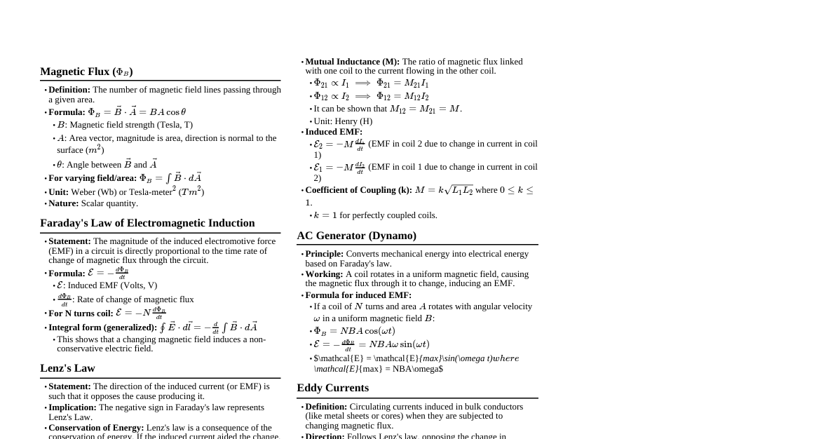
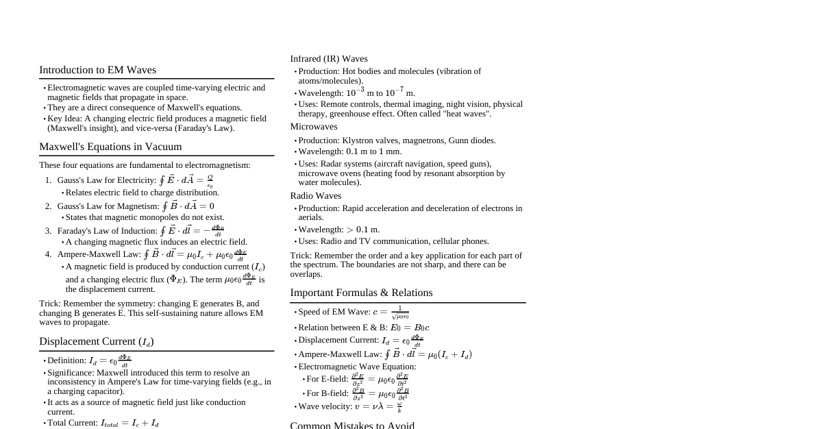
### Magnetic Flux ($\Phi_B$) - **Definition:** The number of magnetic field lines passing through a given area. - **Formula:** $\Phi_B = \vec{B} \cdot \vec{A} = BA \cos\theta$ - Where $B$ is magnetic field strength, $A$ is area, and $\theta$ is the angle between $\vec{B}$ and the normal to the area vector $\vec{A}$. - **Units:** Weber (Wb) or Tesla-meter² ($T \cdot m^2$). ### Faraday's Law of Electromagnetic Induction - **Statement:** The magnitude of the induced electromotive force (EMF) in a circuit is directly proportional to the rate of change of magnetic flux through the circuit. - **Formula:** $\varepsilon = -\frac{d\Phi_B}{dt}$ - For N turns in a coil: $\varepsilon = -N\frac{d\Phi_B}{dt}$ - The negative sign indicates the direction of induced EMF (Lenz's Law). - **Units:** Volt (V). ### Lenz's Law - **Statement:** The direction of the induced current (or EMF) is such that it opposes the cause producing it (i.e., the change in magnetic flux). - **Consequence:** Conservation of energy. ### Motional EMF - **Definition:** EMF induced due to the motion of a conductor in a magnetic field. - **Formula for a straight conductor:** $\varepsilon = (Bvl) \sin\theta$ - Where $B$ is magnetic field, $v$ is velocity of conductor, $l$ is length of conductor, and $\theta$ is the angle between $\vec{v}$ and $\vec{B}$. - If $\vec{v}$, $\vec{B}$, and $\vec{l}$ are mutually perpendicular: $\varepsilon = Bvl$ - **Force on moving charge (Lorentz force):** $\vec{F} = q(\vec{v} \times \vec{B})$ - **Induced current in a closed loop:** $I = \frac{Bvl}{R}$, where $R$ is the resistance of the loop. ### Eddy Currents - **Definition:** Circulating currents induced in bulk conductors when they are subjected to changing magnetic flux. - **Properties:** - Oppose the change in magnetic flux (Lenz's Law). - Can cause damping (e.g., electromagnetic brakes). - Can cause heating (e.g., induction furnaces). ### Self-Induction - **Definition:** The phenomenon of induction of EMF in a coil due to the change in current (and thus magnetic flux) in the same coil. - **Self-Inductance (L):** $L = \frac{\Phi_B}{I}$ - Where $\Phi_B$ is magnetic flux linked with the coil, and $I$ is current in the coil. - **Induced EMF:** $\varepsilon = -L\frac{dI}{dt}$ - **Units of Inductance:** Henry (H) or Wb/A. - **Self-inductance of a solenoid:** $L = \mu_0 n^2 A l$ - Where $\mu_0$ is permeability of free space, $n$ is turns per unit length, $A$ is cross-sectional area, and $l$ is length of solenoid. - **Energy stored in an inductor:** $U_L = \frac{1}{2}LI^2$ ### Mutual Induction - **Definition:** The phenomenon of induction of EMF in one coil due to the change in current in a neighboring coil. - **Mutual Inductance (M):** $M = \frac{\Phi_{B2}}{I_1}$ (Flux in coil 2 due to current in coil 1) - **Induced EMF in coil 2:** $\varepsilon_2 = -M\frac{dI_1}{dt}$ - **Induced EMF in coil 1:** $\varepsilon_1 = -M\frac{dI_2}{dt}$ - **Units of Mutual Inductance:** Henry (H). - **Mutual inductance for two coaxial solenoids:** $M = \mu_0 n_1 n_2 A l$ - Where $n_1, n_2$ are turns per unit length, $A$ is common cross-sectional area, $l$ is common length. - **Coefficient of Coupling (k):** $k = \frac{M}{\sqrt{L_1 L_2}}$ (where $0 \le k \le 1$) ### AC Generator - **Principle:** Converts mechanical energy into electrical energy based on electromagnetic induction. - **Induced EMF in a rotating coil:** $\varepsilon = NBA\omega \sin(\omega t)$ - Where $N$ is number of turns, $B$ is magnetic field, $A$ is area of coil, $\omega$ is angular velocity. - **Peak EMF:** $\varepsilon_{max} = NBA\omega$ ### LC Oscillations - **Definition:** Electrical oscillations occurring in a circuit containing an inductor (L) and a capacitor (C). - **Angular Frequency:** $\omega = \frac{1}{\sqrt{LC}}$ - **Frequency:** $f = \frac{1}{2\pi\sqrt{LC}}$ - **Energy conservation:** Total energy $U = U_L + U_C = \frac{1}{2}LI^2 + \frac{1}{2}\frac{q^2}{C}$ (constant) ### Transformers - **Principle:** Mutual induction. Used to change AC voltage levels. - **Voltage Ratio:** $\frac{V_s}{V_p} = \frac{N_s}{N_p}$ - **Current Ratio (for ideal transformer):** $\frac{I_p}{I_s} = \frac{N_s}{N_p}$ - Where $V_p, I_p, N_p$ are primary voltage, current, and turns; $V_s, I_s, N_s$ are secondary voltage, current, and turns. - **Power (ideal transformer):** $P_p = P_s \implies V_p I_p = V_s I_s$