Electrical Technician Interview Test
Cheatsheet Content
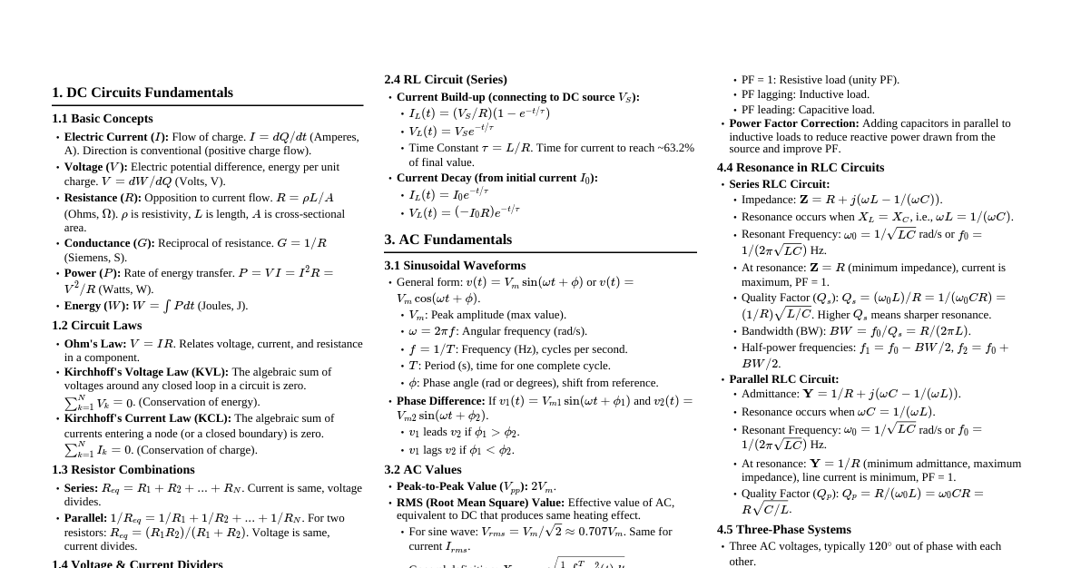
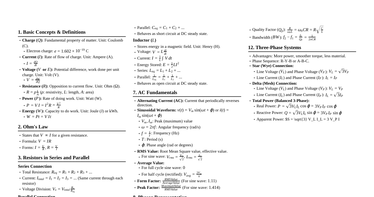
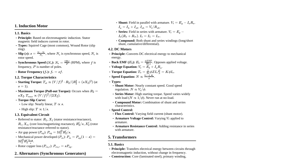
Basic Electrical Concepts Ohm's Law: $V = IR$ $V$: Voltage (Volts) $I$: Current (Amperes) $R$: Resistance (Ohms) Power Law: $P = VI = I^2R = \frac{V^2}{R}$ $P$: Power (Watts) Series Circuits: Current is same: $I_{total} = I_1 = I_2 = ...$ Voltage adds up: $V_{total} = V_1 + V_2 + ...$ Resistance adds up: $R_{total} = R_1 + R_2 + ...$ Parallel Circuits: Voltage is same: $V_{total} = V_1 = V_2 = ...$ Current adds up: $I_{total} = I_1 + I_2 + ...$ Reciprocal resistance adds up: $\frac{1}{R_{total}} = \frac{1}{R_1} + \frac{1}{R_2} + ...$ AC vs. DC: AC (Alternating Current): Direction and magnitude change periodically (e.g., household power). DC (Direct Current): Flows in one direction with constant magnitude (e.g., batteries). Electrical Components Common components and their functions: Component Symbol Function Resistor Limits current flow. Capacitor Stores electrical energy in an electric field. Blocks DC, passes AC. Inductor Stores energy in a magnetic field. Blocks AC, passes DC. Diode Allows current flow in one direction only. Transformer Changes AC voltage levels (steps up/down). Switch Opens or closes a circuit. Circuit Breaker Protects circuits from overcurrent. Electrical Safety LOTO (Lockout/Tagout): Procedure to ensure machinery is properly shut off and cannot be restarted prior to the completion of maintenance or repair work. PPE (Personal Protective Equipment): Insulated gloves, safety glasses, hard hat, fire-resistant clothing, safety shoes. Arc Flash: A dangerous electrical explosion causing severe burns and other injuries. Grounding: Connecting electrical systems to the earth to provide a safe path for fault currents. Fuses & Circuit Breakers: Overcurrent protection devices. Fuses melt and open the circuit; breakers trip and can be reset. GFCI (Ground Fault Circuit Interrupter): Detects imbalances in current flow and quickly shuts off power to prevent electric shock. Test Equipment & Measurements Multimeter: Measures voltage (Volts), current (Amperes), and resistance (Ohms). To measure voltage, connect in parallel with the component. To measure current, connect in series (break the circuit). To measure resistance, connect across the component (power off). Clamp Meter: Measures AC current without breaking the circuit by sensing the magnetic field around the conductor. Megohmmeter (Megger): Measures high resistance, typically used for insulation testing. Continuity Tester: Checks if a circuit path is complete (low resistance). Phase Rotation Meter: Determines the phase sequence in three-phase systems. Motors & Controls DC Motors Operate on direct current. Speed can be controlled by varying armature voltage or field current. Types: Shunt, Series, Compound, Permanent Magnet. AC Motors Operate on alternating current. Induction Motors: Most common type, robust, simple construction. Squirrel cage and Wound rotor types. Synchronous Motors: Run at a constant speed (synchronous speed) regardless of load. Three-Phase Motors: Widely used in industrial applications due to efficiency and self-starting torque. Motor Control Components Contactor: Electrically operated switch for switching a power circuit. Motor Starter: Combines a contactor with overload protection. Variable Frequency Drive (VFD): Controls motor speed by varying frequency and voltage. Overload Relay: Protects motors from excessive current that can cause overheating. Transformers Principle: Mutual induction. Turns Ratio: $\frac{N_P}{N_S} = \frac{V_P}{V_S} = \frac{I_S}{I_P}$ $N_P, N_S$: Number of turns in primary/secondary coils $V_P, V_S$: Primary/secondary voltage $I_P, I_S$: Primary/secondary current Types: Step-up (increases voltage), Step-down (decreases voltage), Isolation (same voltage, isolates circuits). Losses: Core losses (hysteresis, eddy currents), Copper losses ($I^2R$). Wiring & Installation Conductor Sizing Based on current carrying capacity (ampacity), voltage drop, and short-circuit rating. AWG (American Wire Gauge) or mm$^2$ (metric). Smaller AWG number = larger wire. Conduit Protects electrical wiring. Types: EMT (Electrical Metallic Tubing), RMC (Rigid Metal Conduit), PVC (Polyvinyl Chloride). Junction Boxes Enclose electrical connections to protect them and prevent hazards. National Electrical Code (NEC) / Local Codes Set standards for safe electrical installation. Key areas: grounding, overcurrent protection, wiring methods, equipment clearance. Troubleshooting Techniques Symptom Analysis: Understand the problem description. Visual Inspection: Look for obvious damage, loose connections, burnt components. Verify Power: Check for voltage at the source. Check Fuses/Breakers: Ensure they are not tripped or blown. Continuity Checks: Verify closed circuits where expected. Resistance Checks: Measure component resistance (e.g., motor windings, heating elements). Voltage Drops: Measure voltage across components to locate open circuits or excessive resistance. Current Measurements: Check for overcurrent or no current conditions. Manufacturer's Manuals: Refer to wiring diagrams and troubleshooting guides. Divide and Conquer: Isolate sections of a circuit to pinpoint the fault. Programmable Logic Controllers (PLCs) Function: Industrial digital computers that automate electromechanical processes. Components: CPU, Input/Output (I/O) modules, Power Supply, Programming Device. Programming Language: Ladder Logic is most common (resembles relay logic diagrams). Inputs: Sensors (proximity, limit, photo-electric), Pushbuttons, Switches. Outputs: Contactors, Solenoids, Indicator Lights, Motors. Batteries & UPS Systems Battery Types: Lead-acid, Lithium-ion, NiCad. Series Connection: Increases voltage ($V_{total} = V_1 + V_2 + ...$). Parallel Connection: Increases capacity (Ah) ($Ah_{total} = Ah_1 + Ah_2 + ...$). UPS (Uninterruptible Power Supply): Provides backup power during outages and protects against power fluctuations. Important Formulas & Conversions Frequency: $f = \frac{1}{T}$ (Hz), where $T$ is period (seconds). Reactance: Inductive: $X_L = 2\pi fL$ (Ohms) Capacitive: $X_C = \frac{1}{2\pi fC}$ (Ohms) Impedance: $Z = \sqrt{R^2 + (X_L - X_C)^2}$ (Ohms) for RLC series circuit. Power Factor: $PF = \cos(\theta) = \frac{P_{real}}{P_{apparent}}$ Efficiency: $\eta = \frac{P_{out}}{P_{in}} \times 100\%$ kW to kVA: $kVA = \frac{kW}{PF}$ Horsepower to Watts: $1 \text{ hp} \approx 746 \text{ Watts}$ Common Electrical Symbols Component Symbol Component Symbol Battery Ground Fuse Lamp Ammeter A Voltmeter V Ohmmeter $\Omega$ Motor M