Alternating Current Essentials
Cheatsheet Content
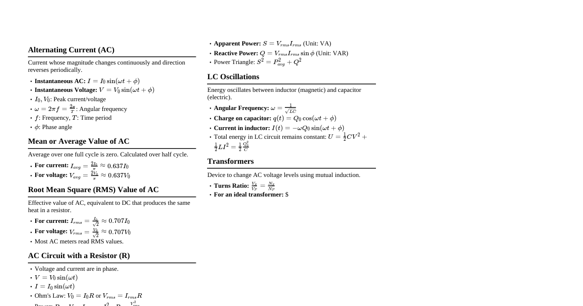
Simple Harmonic Motion (SHM) Condition: $F = -kx$ Equation: $\frac{d^2x}{dt^2} + \omega^2x = 0$ Solution: $x = A \sin(\omega t + \phi)$, where $\phi$ is the initial phase. Amplitude: $A$ Angular Frequency: $\omega = \sqrt{K/m}$ Note: We can add/subtract sinusoidal functions using phasors. AC Generator Working Principle: Faraday's Law - An EMF is induced whenever $\Phi_B$ linked with a coil changes. The EMF is equal to the rate of change of $\Phi_B$ with respect to time. $EMF = (NBA\omega) \sin(\omega t)$ Peak value of voltage: $E_0 = NBA\omega$ Angular velocity: $\omega = 2\pi f$ Standard EMF in India: $220\,V$, $50\,Hz$ Condition for Current/Voltage to be Alternating: Amplitude Constant Time period $T$ (or frequency $f$) Constant Proper Harmonic Content (PHC) and No Modulation Content (NMC) Concept of Average & RMS Value Average Value: $\langle I \rangle = \frac{1}{t_2 - t_1} \int_{t_1}^{t_2} I \, dt$ Mean Square: $\langle I^2 \rangle = \frac{1}{t_2 - t_1} \int_{t_1}^{t_2} I^2 \, dt$ Root Mean Square (RMS) Value: $I_{rms} = \sqrt{\langle I^2 \rangle} = \sqrt{\frac{1}{t_2 - t_1} \int_{t_1}^{t_2} I^2 \, dt}$ RMS value is our effective value, which is reported for AC. For a complete cycle ($0 \to T$): $I_{avg} = 0$ $I_{rms} = I_0 / \sqrt{2}$ For a half cycle ($0 \to T/2$): $I_{avg} = 2I_0 / \pi$ $I_{rms} = I_0 / \sqrt{2}$ AC Circuits 1. Resistor (R) Circuit $E = E_0 \sin(\omega t)$ $I = I_0 \sin(\omega t)$ Peak EMF: $E_0$ RMS EMF: $E_0 / \sqrt{2}$ Peak Current: $I_0 = E_0 / R$ RMS Current: $I_{rms} = I_0 / \sqrt{2}$ Voltage and current are in phase ($\phi = 0$). 2. Inductor (L) Circuit $E = E_0 \sin(\omega t)$ $I = I_0 \sin(\omega t - \pi/2)$ Peak EMF: $E_0$ RMS EMF: $E_0 / \sqrt{2}$ Peak Current: $I_0 = E_0 / X_L$, where $X_L = \omega L$ (Inductive Reactance). RMS Current: $I_{rms} = I_0 / \sqrt{2}$ Current lags voltage by $\pi/2$. 3. Capacitor (C) Circuit $E = E_0 \sin(\omega t)$ $I = I_0 \sin(\omega t + \pi/2)$ Peak EMF: $E_0$ RMS EMF: $E_0 / \sqrt{2}$ Peak Current: $I_0 = E_0 / X_C$, where $X_C = 1 / (\omega C)$ (Capacitive Reactance). RMS Current: $I_{rms} = I_0 / \sqrt{2}$ Current leads voltage by $\pi/2$. 4. RL Circuit (Series) $E = E_0 \sin(\omega t)$ $I = I_0 \sin(\omega t - \phi)$ Net Impedance: $Z = \sqrt{R^2 + X_L^2}$ Phase difference: $\tan \phi = X_L / R$ Voltage across Resistor: $V_R = I_{rms} R$ Voltage across Inductor: $V_L = I_{rms} X_L$ Current lags voltage. 5. RC Circuit (Series) $E = E_0 \sin(\omega t)$ $I = I_0 \sin(\omega t + \phi)$ Net Impedance: $Z = \sqrt{R^2 + X_C^2}$ Phase difference: $\tan \phi = X_C / R$ Voltage across Resistor: $V_R = I_{rms} R$ Voltage across Capacitor: $V_C = I_{rms} X_C$ Current leads voltage. 6. LCR Circuit (Series) $E = E_0 \sin(\omega t)$ $I = I_0 \sin(\omega t \pm \phi)$ Net Impedance: $Z = \sqrt{R^2 + (X_L - X_C)^2}$ Phase difference: $\tan \phi = (X_L - X_C) / R$ Power in AC Circuits Average Power: $P_{avg} = V_{rms} I_{rms} \cos \phi = \frac{V_0 I_0}{2} \cos \phi$ Power Factor: $\cos \phi$ Wattful Current: $I_{rms} \cos \phi$ Wattless Current: $I_{rms} \sin \phi$ Resonance in Series LCR Circuit Condition: $X_L = X_C$ Net Impedance: $Z = R$ (minimum) Phase difference between $V$ & $I$ is $0$ ($\phi = 0$) Power factor: $\cos \phi = 1$ Resonant frequency: $\omega_0 = 1 / \sqrt{LC}$ or $f_0 = 1 / (2\pi \sqrt{LC})$ Current $I_0 = E_0 / R$ (maximum) Bandwidth: $2\Delta\omega = \omega_2 - \omega_1 = R/L$ Quality Factor (Q-factor): $Q = \omega_0 L / R = 1 / (R \sqrt{LC})$ Transformer Working Principle: Mutual Inductance Primary side: $N_p$ turns, $E_p$ voltage, $I_p$ current Secondary side: $N_s$ turns, $E_s$ voltage, $I_s$ current Ratio: $E_s / E_p = N_s / N_p$ For a 100% efficient transformer: $E_s / E_p = N_s / N_p = I_p / I_s$ Step-up Transformer: $N_s > N_p \Rightarrow E_s > E_p \Rightarrow I_s Step-down Transformer: $N_s I_p$ Losses in Transformer Copper Losses: Heat loss in primary & secondary windings. Remedy: Use thick wire. Iron Loss: Hysteresis Loss: Due to repeated magnetization and demagnetization of the core. Remedy: Use soft iron core (low retentivity). Eddy Current Loss: Induced circulating currents in the core. Remedy: Use laminated iron core. LC Oscillation Periodic oscillation of energy between capacitor and inductor. Equation: $\frac{d^2q}{dt^2} + \frac{1}{LC}q = 0$ (SHM) Initial Energy: $U = Q^2 / (2C)$ Charge at any time: $q = Q \sin(\omega t + \phi)$ Current at any time: $I = \frac{dq}{dt} = Q\omega \cos(\omega t + \phi)$ Maximum current: $I_{max} = Q\omega = Q/\sqrt{LC}$ Resonant frequency: $\omega = 1/\sqrt{LC}$ Time period of oscillation: $T = 2\pi\sqrt{LC}$ Frequency: $f = 1/(2\pi\sqrt{LC})$ Parallel Combination (AC Circuits) Currents are different, Voltage is same ($V_{total} = V_R = V_L = V_C$). Net Current: $I_{net} = \sqrt{I_R^2 + (I_C - I_L)^2}$ Net Impedance: $Z = \frac{1}{\sqrt{\frac{1}{R^2} + (\frac{1}{X_C} - \frac{1}{X_L})^2}}$ Peak value of current: $I_0 = E_0 / Z$ Phase angle: $\tan \phi = \frac{I_C - I_L}{I_R} = \frac{V/X_C - V/X_L}{V/R} = \frac{1/X_C - 1/X_L}{1/R}$