Alternating Currents & Phasors
Cheatsheet Content
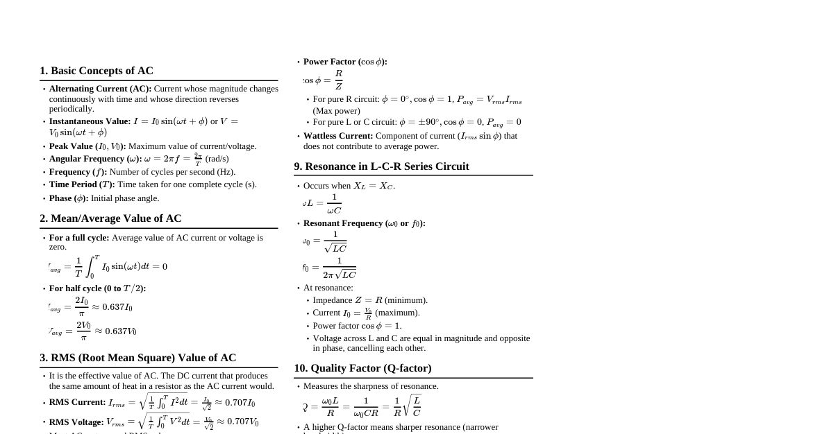
### AC Circuit Basics - **Alternating Current (AC):** Current whose magnitude and direction vary periodically, typically sinusoidally. - **Instantaneous Voltage:** $v(t) = V_m \sin(\omega t + \phi_v)$ - **Instantaneous Current:** $i(t) = I_m \sin(\omega t + \phi_i)$ - $V_m, I_m$: Peak voltage and current - $\omega$: Angular frequency (rad/s), $\omega = 2\pi f$, where $f$ is frequency (Hz) - $\phi_v, \phi_i$: Phase angles for voltage and current - **RMS (Root Mean Square) Values:** - $V_{rms} = V_m / \sqrt{2}$ - $I_{rms} = I_m / \sqrt{2}$ - Used for power calculations and standard AC measurements. ### Phasor Representation - **Definition:** A rotating vector used to represent sinusoidal quantities (voltage, current) in AC circuits. - **Length:** Corresponds to the peak ($V_m, I_m$) or RMS ($V_{rms}, I_{rms}$) value. - **Angle:** Represents the phase angle ($\phi_v, \phi_i$) relative to a reference. - **Rotation:** Rotates counter-clockwise with angular frequency $\omega$. - **Complex Plane Representation:** - Voltage: $\vec{V} = V_m \angle \phi_v = V_m (\cos\phi_v + j\sin\phi_v)$ - Current: $\vec{I} = I_m \angle \phi_i = I_m (\cos\phi_i + j\sin\phi_i)$ - $j = \sqrt{-1}$ (imaginary unit, often $i$ in math) ### Components in AC Circuits #### Resistor (R) - **Voltage:** $v_R(t) = V_R \sin(\omega t)$ - **Current:** $i_R(t) = I_R \sin(\omega t)$ - **Relationship:** $V_R = I_R R$ (Ohm's Law) - **Phase:** Voltage and current are in phase ($\phi_v = \phi_i$). - **Phasor:** $\vec{V}_R = I_R R \angle 0^\circ$, $\vec{I}_R = I_R \angle 0^\circ$ (if current is reference) #### Inductor (L) - **Voltage:** $v_L(t) = L \frac{di_L}{dt}$ - **Current:** $i_L(t) = I_L \sin(\omega t)$ - **Voltage:** $v_L(t) = I_L \omega L \sin(\omega t + 90^\circ)$ - **Inductive Reactance:** $X_L = \omega L$ (Ohms) - **Relationship:** $V_L = I_L X_L$ - **Phase:** Voltage leads current by $90^\circ$ (or current lags voltage by $90^\circ$). - **Phasor:** $\vec{V}_L = I_L X_L \angle 90^\circ$, $\vec{I}_L = I_L \angle 0^\circ$ (if current is reference) #### Capacitor (C) - **Current:** $i_C(t) = C \frac{dv_C}{dt}$ - **Voltage:** $v_C(t) = V_C \sin(\omega t)$ - **Current:** $i_C(t) = V_C \omega C \sin(\omega t + 90^\circ)$ - **Capacitive Reactance:** $X_C = 1 / (\omega C)$ (Ohms) - **Relationship:** $V_C = I_C X_C$ - **Phase:** Current leads voltage by $90^\circ$ (or voltage lags current by $90^\circ$). - **Phasor:** $\vec{V}_C = I_C X_C \angle -90^\circ$, $\vec{I}_C = I_C \angle 0^\circ$ (if current is reference) ### Impedance (Z) - **Definition:** The total opposition to current flow in an AC circuit, combining resistance and reactance. - **Complex Quantity:** $Z = R + jX$, where $X$ is net reactance ($X_L - X_C$). - **Magnitude:** $|Z| = \sqrt{R^2 + X^2}$ - **Phase Angle:** $\theta_Z = \arctan(X/R)$ - **Ohm's Law for AC:** $\vec{V} = \vec{I} \vec{Z}$ - **Units:** Ohms ($\Omega$) #### Series RLC Circuit - **Total Impedance:** $Z = R + j(X_L - X_C)$ - **Magnitude:** $|Z| = \sqrt{R^2 + (X_L - X_C)^2}$ - **Phase Angle:** $\phi = \arctan\left(\frac{X_L - X_C}{R}\right)$ - If $\phi > 0$: Inductive circuit (voltage leads current) - If $\phi ### Phasor Diagrams - **Purpose:** Visual representation of voltage and current phasors, showing their relative magnitudes and phase differences. - **Steps to Draw:** 1. **Choose a Reference:** For series circuits, current is often the reference ($\vec{I}$ along the positive x-axis). For parallel circuits, voltage is often the reference ($\vec{V}$ along the positive x-axis). 2. **Draw Reference Phasor:** Draw the reference phasor (e.g., $\vec{I}$ or $\vec{V}$) along the positive real axis. 3. **Draw Component Phasors:** - **Resistor:** Voltage phasor ($\vec{V}_R$) is in phase with current ($\vec{I}$). - **Inductor:** Voltage phasor ($\vec{V}_L$) leads current ($\vec{I}$) by $90^\circ$. - **Capacitor:** Voltage phasor ($\vec{V}_C$) lags current ($\vec{I}$) by $90^\circ$. 4. **Vector Sum:** Add the voltage phasors (for series) or current phasors (for parallel) vectorially to find the total voltage or current. - For series: $\vec{V}_{\text{total}} = \vec{V}_R + \vec{V}_L + \vec{V}_C$ - For parallel: $\vec{I}_{\text{total}} = \vec{I}_R + \vec{I}_L + \vec{I}_C$ #### Example: Series RLC Phasor Diagram (Current as Reference) - $\vec{I}$ is on the x-axis. - $\vec{V}_R$ is in phase with $\vec{I}$. - $\vec{V}_L$ is $90^\circ$ ahead of $\vec{I}$. - $\vec{V}_C$ is $90^\circ$ behind $\vec{I}$. - $\vec{V}_{\text{total}}$ is the vector sum, forming a right triangle with $\vec{V}_R$ and $(\vec{V}_L - \vec{V}_C)$. ### Power in AC Circuits - **Instantaneous Power:** $p(t) = v(t) i(t)$ - **Apparent Power (S):** - $S = V_{rms} I_{rms}$ (magnitude) - $S = P + jQ$ (complex power) - Units: Volt-Amperes (VA) - **Real Power (P) / Average Power:** - $P = V_{rms} I_{rms} \cos\phi = I_{rms}^2 R = V_{rms}^2 / R$ - Units: Watts (W) - Power dissipated by the resistance. - **Reactive Power (Q):** - $Q = V_{rms} I_{rms} \sin\phi = I_{rms}^2 X = V_{rms}^2 / X$ - Units: Volt-Ampere Reactive (VAR) - Power exchanged between source and reactive components (L, C). - **Power Factor (PF):** - $PF = \cos\phi = P/S$ - $\phi$ is the phase difference between total voltage and total current. - Lagging PF: Inductive circuit (current lags voltage). - Leading PF: Capacitive circuit (current leads voltage). ### Resonance in AC Circuits - **Definition:** Occurs when the inductive reactance equals the capacitive reactance ($X_L = X_C$). - **Resonant Frequency ($\omega_0$ or $f_0$):** - $\omega_0 L = 1/(\omega_0 C) \Rightarrow \omega_0 = 1/\sqrt{LC}$ (rad/s) - $f_0 = 1/(2\pi\sqrt{LC})$ (Hz) #### Series Resonance - **Impedance:** $Z = R$ (minimum impedance, purely resistive). - **Current:** Maximum current for a given voltage. - **Phase:** Voltage and current are in phase (PF = 1). - **Voltage Magnification:** $V_L$ and $V_C$ can be much larger than source voltage. #### Parallel Resonance - **Impedance:** $Z$ is maximum (ideally infinite, purely resistive). - **Current:** Minimum current from source for a given voltage. - **Phase:** Voltage and current are in phase (PF = 1). - **Current Magnification:** Current circulating in L-C loop can be much larger than source current.